Let’s Do the Twist
June 1, 2004 for QuietFlyer Magazine
In an electric model, the possibility of the electric power system interfering with the radio control system has been greatly reduced by improvements in receiver technology in the last decade. However, interference can still happen, especially if care is not taken in installing both systems.
Electricity and Magnetism
Both the power system (motor battery, speed control, and motor), and the radio system (receiver battery, receiver, and servos) use electricity and magnetism to do their work.
The power system passes an electric current from the motor battery through the speed control and into the motor. There the current passes through the armature windings to create a magnetic field that interacts with the permanent magnets in the motor, causing the armature to turn. As the armature becomes aligned with the motor’s permanent magnets, the current is switched off and then back on in the opposite direction so that the armature keeps on turning (see How Electric Motors Work from the December 2002 issue of QuietFlyer). In a brushed motor, this switching is done by the commutator; in a brushless motor it is done by the speed control.
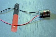
A circuit is like a loop of wire, and produces a phantom magnet when current flows through it. If the current is being switched on and off, the magnet will emit radio waves.
The inside of the motor is not the only place where a magnetic field is generated. Any wire with a steady current flowing through it will generate a steady magnetic field. Whenever the current is switched on and off (or reversed in direction), a disturbance is created in the field. Think of the magnetic field as a body of water, and the on/off switching as dropping a stone in the water.
These magnetic ripples, called "electromagnetic radiation", propagate through the universe at the speed of light. Another term for electromagnetic radiation is "radio wave". In essence, your plane’s electric power system is a radio transmitter.
Now let’s look at the radio control system, whose main component is the receiver. The receiver’s job is to detect radio waves, extract servo position information from them, and pass pulses on to the servos to tell them what they should be doing.
The most important part of the receiver is the antenna, which is just a wire hanging out in the breeze. Remember that current flowing through a wire causes a magnetic field, and that pulsating current causes radio waves. The reverse is also true; radio waves cause a pulsating current in any wire that encounters them, a process known as "induction".
The world is full of radio transmitters, all trying to transmit to one or more receivers. There are two things that prevent every receiver from simultaneously receiving all the world’s transmissions: distance and frequency.
Radio waves are governed by the "inverse square law", which states that the strength of the waves is inversely proportional to the square of the distance from the transmitter, much like the height of the ripples in a pond are inversely proportional to the distance from where the stone fell in. What this means is that the radio waves from any given transmitter will be too weak to detect if the transmitter is too far away.
Frequency is the rate, in cycles per second, at which the radio transmitter is pulsing the current on and off, and thus the rate at which the radio waves cause a pulsating current in the receiver’s antenna. The receiver is designed to only detect pulses that occur at a specific frequency, ignoring any pulses that are arriving at a different frequency.
This is very much like being in a large crowded room, where a few people are speaking English, and everyone else is speaking languages you do not understand (let’s assume you only understand English). Although all the languages are entering you ears (antenna), your brain (receiver) processes only the one it understands, filtering out the rest. And, so long as only one of the English speakers is near you, you can easily ignore the others that are further away.
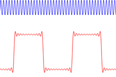
A low frequency square wave such as that from motor commutation (bottom) has edges that contain high frequency sine waves, which might be mistaken for a radio signal (top) by a receiver.
What is Interference?
We’ve noted above that among other things, an electric power system is a form of radio transmitter. This transmitter is very close to the radio receiver in the model, which suggests that interference is a possibility. Which begs the question, why does it work at all?
Frequency comes to the rescue. Our radio control systems operate at frequencies of about 72 million cycles per second (72 MegaHertz, or 72 MHz). On the other hand, a three-pole motor, spinning at 10,000 rpm, produces electromagnetic radiation at a frequency of about 500 cycles per second (500 Hertz, or 500 Hz), and some more at the speed control’s switching frequency, usually about 2000 Hz. These frequencies are not even close to the receiver’s frequency so theoretically, no interference can occur. Unfortunately, it’s not that easy.
Properly generated radio waves are pure sine waves. They don’t just turn on and off, but rather pulsate smoothly, just like the ripples in a pond do not have sharp edges. The switching of a motor on the other hand is very sudden, but tends to wobble a bit at a much higher frequency. This "ringing", as it is called, can be in a frequency that the receiver detects (figure 1). In the crowded room analogy, if one of the nearby speakers was speaking Latin, you may recognize the occasional word and confuse it with the words of the nearby English speaker.
The other issue is that of shear volume. A sufficiently strong nearby signal can drown out the desired signal, even if the nearby signal is on a completely different frequency. If the English speaker to which you were listening was five feet away, and then someone started shouting into your ear in Swahili, you would not be able to understand the English no matter how little sense the louder voice makes to you.
Finally, a radio receiver contains several intermediate stages that work at lower frequencies than that being received (usually 10.7 MHz and 455 kHz). If the receiver itself is close to a source of unwanted signals at these frequencies, interference can occur.
Reducing Interference
The first steps in solving interference problems always involve reducing it at the source and/or shielding the receiver from it. In our crowded room, asking the Swahili speaker to be more quiet and/or putting a wall between him and yourself, will make it easier to once again understand the English speaker.
The most common reason for motor-caused interference is sparking at the commutator. A spark is electrical noise, and noise is just a signal on many frequencies at the same time. This is the electrical equivalent to shouting loudly in every language at once, which will confuse almost any listener. The cure for this is generally proper adjustment of the motor timing to minimize the sparking.
The next major source of interference is radio waves that are emitted by the motor wires. In small models, where the motor, speed control, and battery are close together, this is not usually a problem. In larger models, where long wire runs are involved, it can cause so much interference as to make the model uncontrollable.
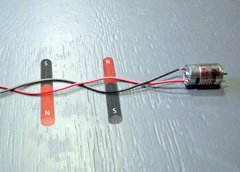
Twisting the wires making up a circuit results in many smaller magnets with opposing polarity, which cancel each other out.
Twist It!
Recall that pulsating current in a wire will produce radio waves. In any circuit, such as a motor power system, there will be pulsating currents in the wires between the speed control and motor. The magnetic field around a wire always has the same polarity for a given direction of current flow. As the current flows through the circuit from the battery, through the speed control, motor, back through the speed control, and back to the battery, a very strong field is produced, with the fields at each little section of the wire combining to make one big field. The circuit is essentially a coreless electromagnet with only a single turn of wire (figure 2).
By twisting the wires, we produce many small electromagnets, instead of one large one. Furthermore, these many small magnets are pointing in alternating directions. If we were very close to one of these magnets, we could still detect it, but once we are a small distance away, the adjacent opposing magnets will cancel it out (figure 3).
So, as the motor current switches on and off or back and forth, the electromagnetic radiation generated by the many small magnets created by the twisted wires will also cancel out, limiting the transmission of interference.
As long as the receiver is not too close to the twisted wires, it will not detect any of the radio waves being produced, and will hear only the desired radio waves from our radio control transmitter, even though it is much further away.
If we rely solely on the inverse square law, the receiver and its antenna would have to be a long way from the interference producing wires. With the canceling effect produced by twisting the wires, it can be much closer (but should still be kept as far away as is practical).
Servo Leads
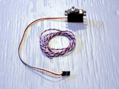
In a concession to mass production, modern servos like this Hitec HS-81 have flat parallel leads. Older servos used twisted leads like this vintage Ace R/C servo lead (center).
In the early days of radio control, when servos were built by modelers themselves or were hand made in low volumes by manufacturers such as Kraft or Ace, servos came with twisted or braided leads. Besides making the leads more flexible, this also helped to reduce interference problems (which ironically, was less of a problem back in the dark ages, when planes were powered by glow engines instead of electric motors).
In the case of a servo, it can be both a source of interference, and a conduit by which outside interference (such as from the motor wiring) can enter the receiver.
Because the servos are connected to the receiver, the servo leads can also act like a receiving antenna, picking up outside interference and conducting it (as opposed to transmitting it) to the receiver. This is less of a problem than it sounds, because the servo-driving circuitry in the receiver is generally well separated from the radio-receiving part of the receiver. However, they are not completely disconnected, since they share the same power supply.
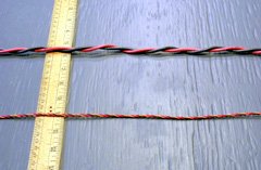
When running both a speed control receiver lead (bottom) and power leads (top) to a distant brushless motor and its speed control, twist both, and keep them well separated.
The bigger issue is that the servo itself contains a motor. It too can produce interference, which will then be transmitted by the servo leads, and possibly picked up by the receiver antenna. By twisting or braiding the servo leads much like the power system’s motor leads, the potential for problems can be reduced. It’s also worthwhile to make an effort to keep the receiver antenna away from the servos and the servo leads.
Multi-motor Models
Twisting of motor leads is especially important in multi-motored models, where the motors are often a long way away from the speed control. The longer motor leads are more effective at transmitting interference, making it more important than ever to twist them.
Brushless Motor Systems
Although brushless motors don’t have a commutator to produce interference-causing sparks, they are not immune from producing interference. There are still high switching frequencies with sharp-edged wave forms involved in the operation of the motor. Fortunately, a brushless speed control is usually very close to the motor, and the three leads connecting them are often only an inch or two long (for many sensorless speed controls, short leads are required to ensure proper operation).
In a multi-motor brushless model, there will generally be one speed control per motor, with long power leads to the centrally located battery, and long servo-type leads to the centrally located receiver. These should be kept as far apart as is practical, and each lead should be twisted.
Related Articles
If you've found this article useful, you may also be interested in:
- Measuring Up
- How Electric Motors Work
- More Electric Flight Terms
- Electric Flight Terminology
- Electromagnetic Interference Reduction

If you've found this article useful, consider leaving a donation in Stefan's memory to help support stefanv.com
Disclaimer: Although every effort has been made to ensure accuracy and reliability, the information on this web page is presented without warranty of any kind, and Stefan Vorkoetter assumes no liability for direct or consequential damages caused by its use. It is up to you, the reader, to determine the suitability of, and assume responsibility for, the use of this information. Links to Amazon.com merchandise are provided in association with Amazon.com. Links to eBay searches are provided in association with the eBay partner network.
Copyright: All materials on this web site, including the text, images, and mark-up, are Copyright © 2025 by Stefan Vorkoetter unless otherwise noted. All rights reserved. Unauthorized duplication prohibited. You may link to this site or pages within it, but you may not link directly to images on this site, and you may not copy any material from this site to another web site or other publication without express written permission. You may make copies for your own personal use.
John W Juechter
December 26, 2008
Congratulations! I think you have done a wonderful job explaining the cause and effect of internal radio interference. And your language examples are extremely well chosen as illustrations. It would have even better had you been able to convey how to determine how many turns per inch of twist are needed.
Dan C.
October 02, 2012
Great article! Question: Is it better to have a long lead from the motors to the ESC’s and a short lead from the ESC’s to the flight controller, or the other way around?
Judy L Akers
June 06, 2014
I wonder if you know how I can use amouse to control an RC toy car or a toy jet instead of cotrolling the mouse icone on the PC screen. The use of two resistors or IR could be the same as using the joystick of RC Transmitter and the use of encoder on the transmitter to be decoded later on the reciever for the functions.
If you have or know of such project on the web, please let me know of it.
I appreciate your efforts and reply in advance.
judylynnakers@gmail.com