How Electric Motors Work
December 1, 2002 for QuietFlyer Magazine
Much has been written about choosing the right motor, estimating performance, installing the motor in your plane, and so on. This month, I’ve decided to go back to basics and describe how the motor actually works. Do you need to know this to fly electric models? Probably not, but a good understanding of the functioning of a motor can help you diagnose problems. And some people, myself included, like to know how everything works. So, if you’re interested, read on!
I’m going to start with the very basics, so if you already know some of it, feel free to skip ahead. I won’t be offended.
Magnets
The fundamental driving force behind all electric motors, whether brushed or brushless, AC or DC, is magnetism. We’ve probably all played with magnets at some time or other, and have learned about them in science class in elementary school.
Recall that any magnet has a north pole and a south pole (it just so happens that the earth is a magnet whose poles happen to correspond very roughly to the geographical poles, hence the names for the magnet’s poles). If you take two bar shaped magnets and line them up, they will be attracted to one another if one’s north pole is next to the other’s south pole. If you line them up north to north or south to south, they will repel each other. Opposites attract.
Consider an assembly of three magnets, as shown in Figure 1. The left and right hand magnets are fixed to some surface, and the center magnet is free to rotate about its center.

Figure 1. The central rotating magnet will turn until it is aligned with the two fixed magnets, north pole to south pole.
Because of the attraction of opposite poles, the center magnet will rotate until it is aligned as in Figure 2.
Because the magnet has weight, and thus momentum, it would actually overshoot slightly, and then come back, overshoot again, and so on a few times before settling down.
Now, imagine we could work some magnetic magic and swap the center magnet’s north and south poles just as it overshoots the first time, as shown in Figure 3.

Figure 3. If we magically reverse the poles of the central magnet just before it comes to rest, it will keep turning.
Instead of coming back, it would now be repelled by the fixed magnets, and keep turning so it can align itself in the other direction. Eventually, it would reach the state in Figure 4, which looks suspiciously like Figure 1.
If we perform this pole-swapping every time the center magnet just finishes overshooting the aligned position, it would keep turning forever.
The problem is how to perform this feat of magnetic motion.
Electromagnets
The magnets we play with are called permanent magnets. These objects have a fixed magnetic field that’s always there. The poles are fixed relative to one another and relative to the physical magnet.
Another kind of magnet is the electromagnet. In its simplest form, this consists of an iron bar, wrapped in a coil of wire, as in Figure 5.

Figure 5. An electromagnet is just a piece of iron or other magnetic metal with a wire coil wrapped around it.
By itself it does nothing. However, if you pass an electric current through the wire, a magnetic field is formed in the iron bar, and it becomes a magnet, as in Figure 6.
If you turn off the current, it stops being a magnet (that’s a bit of a simplification, since in reality, it ends up remaining a weak magnet, but we needn’t concern ourselves with that for the moment).
So far, the electromagnet already seems quite useful, since we can use it to pick up iron, steel, or nickel objects, carry them somewhere, and then drop them by just turning off the power (wrecking yard cranes do this with entire automobiles).
The really interesting thing about an electromagnet is that its polarity (the location of the north and south poles) depends on the direction of current flow. If we pass the current through in the opposite direction, the electromagnet’s poles will be reversed, as shown in Figure 7.
Eureka!
If we replace the central magnet in our set of three magnets with an electromagnet, as in Figure 8, we have the beginnings of an electric motor.

Figure 8. Replacing the central magnet in Figure 1 with an electromagnet gives us the beginnings of a motor.
Now we have two problems to solve: feeding the current to the rotating electromagnet without the wires getting twisted, and changing the direction of the current at the appropriate time.
Both of these problems are solved using two devices: a split-ring commutator, and a pair of brushes. Figure 9 illustrates these.
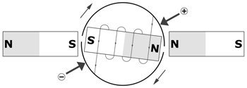
Figure 9. By adding a commutator (the semi-circular arcs) and brushes (the wide arrows), we can change the polarity of the electromagnet as it turns.
The two semicircles are the commutator, and the two arrows are the brushes. The current is applied to the brushes, indicated by the "+" and "-" signs.
With the current as shown, the electromagnet will be repelled by the two permanent magnets, and it will turn clockwise. After it has turned almost half way around, it will be in the state shown in Figure 10.
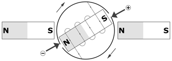
Figure 10. The magnets are almost aligned, but soon, the polarity will reverse, sending the rotating electromagnet on its way around once again.
Then, just as the magnet reaches the aligned state, the split in the commutator passes under the brushes, and then the current through the electromagnet reverses, which takes us back to the condition in Figure 9. As a result, the magnet keeps turning. We have a motor!
Some Terminology
The discussion above has culminated in the design of a simple two-pole, two-slot, permanent magnet, brushed, direct-current (DC) motor.
The term two-pole refers to the fact that there are two permanent magnet poles involved in the operation of the motor, the south pole of the left hand magnet and the north pole of the right hand magnet. The motor would actually work with only one fixed magnet (for example, only the left hand magnet), but would be less powerful and efficient.
The rotating electromagnet is known as the armature. Two-slot means that the armature consists of a single coil of wire around a single bar with only two ends (the term "slot" refers to the gap between the armature ends, since the armature is not typically bar shaped, but has a wider end).
Real Motors
In a real two-pole motor, the two poles are often the two ends of the same magnet. Although the motor may appear to contain two separate magnets, the steel motor case ties them together to act as a single magnet. It’s really as if our motor were built like in Figure 11, with the rotating electromagnet inside a hole in the permanent magnet.
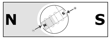
Figure 11. In many motors, the two fixed magnets are really one the two poles of what is effectively one magnet (although it may be made up of two separate magnets connected by the motor housing).
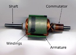
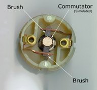
Practical real motors usually have at least a three-slot armature, and a commutator with three segments. There are however still only two brushes. Higher voltage and higher efficiency motors have even more slots (an odd number) and more segments on the commutator (the same as the number of slots), and more brushes (always an even number). Photos 1 and 2 show the armature, commutator, and brushes from a typical low-cost three-slot motor.
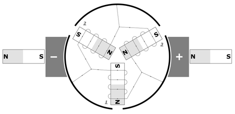
Figure 12 illustrates a three-slot motor in conceptual form. Notice that the brush is now wider, contacting the commutator segments over a wider area, and actually spanning two segments sometimes.
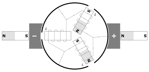
Figure 12. This is a schematic representation of a typical three-slot two-pole brushed motor. The armature has three electromagnets, and three commutator segments. The brushes sometimes contact more than one segment.
Also notice that both ends of electromagnet number 2 are contacting the "-" brush at the particular point in time captured by Figure 12. This means that no current is flowing through electromagnet 2, and only number 1 and 3 are on.
Effectively, the armature is now a pair of electromagnets; number 3 is being attracted by the north pole of the right hand permanent magnet, and number 1 is being repelled.
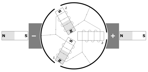
One twelfth of a turn later, as in Figure 13, all three electromagnets have current flowing through them.
Now, electromagnet number 1 is being both repelled by the right hand permanent magnet, and attracted by the left hand one. Number 2 is being repelled by the left magnet, and number 3 is still being attracted by the right magnet.
Another twelfth of a turn later, in Figure 14, electromagnet 1 is being attracted to the left hand magnet, and number 2 is still being repelled.
Electromagnet 3 is turned off. This progression of electromagnets switching on and off continues as the motor turns, eventually returning to the state of Figure 12.
The Brushless Motor
There are a number of drawbacks to the brush and commutator mechanism used in a brushed motor: the brushes cause friction, there is some electrical resistance in the brush-to-commutator interface, and the mechanical switching of the armature current results in sparking, which can cause radio interference. Brushless motors do away with the brushes and commutator to get around these problems. The result is greater efficiency (more output power for a given amount of input power), and less electrical interference.
The basic principles by which a brushless motor operates are exactly the same as those of a brushed motor. Figures 15 and 16 show two stages in the operation of a simple brushless motor.

Figure 15. This is the brushless motor equivalent of Figure 9. The electromagnets are fixed, and the permanent magnet rotates.
Notice that Figure 15 is almost identical to Figure 9, except that there are no brushes and no commutator, and the types of the magnets have been exchanged. The permanent magnets have become electromagnets, and vice versa. The rotating permanent magnet is being repelled by the two electromagnets.

Figure 16. The motor from Figure 15, almost a full turn later. Notice that the electromagnets have changed their polarity.
In Figure 16, almost a full turn later, the polarity of the left and right hand magnets has changed. The rotating magnet is now being pulled into alignment.
The problem to be solved here is how to cause the electromagnets to reverse their polarity at the right time. One could devise some sort of mechanical scheme controlled by the rotating permanent magnet, but this would nullify the main benefits of brushless motors.
Instead, the electromagnets are controlled by external circuitry. This circuitry monitors the current position of the rotating magnet, and energizes the external magnets appropriately to keep the motor turning. This circuitry is part of the brushless electronic speed control (ESC).
There are two ways for a brushless ESC to monitor the position of the rotating magnet. One is by way of magnetic sensors (based on the Hall-effect). These sensors report back to the ESC through a separate set of wires. The other method is known as "sensorless". Roughly, in this method the ESC monitors the three motor power wires for fluctuations caused by the spinning magnets.
Brushless Terminology
Since the electromagnet assembly in a brushless motor remains stationary, it is called a stator instead of an armature. The rotating magnet assembly is called the rotor.
Real Brushless Motors
Just as a real brushed motor rarely has only two poles and a two-slot armature, a real brushless motor rarely has only a two-pole rotor and a two-slot stator. Most commercially available brushless motors have at least four poles, and a nine or more slot stator. However, for purposes of comparison, Figure 17 illustrates a hypothetical two-pole three-slot brushless motor, corresponding to our two-pole three-slot brushed motor.
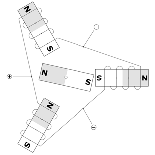
Figure 17. This is a schematic representation of a hypothetical three-slot two-pole brushless motor. The rotor has one permanent magnet (two poles), and the stator has three electromagnets (three slots) and three connection points.
Notice there are three connection points to receive power from the brushless ESC (a motor with more than three stators has them wired in three groups, so there are still only three power leads).
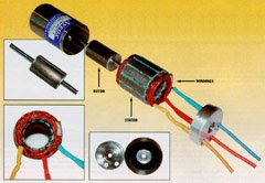
Photo 3. The components of an Aveox 36/30/1.5 brushless motor.
www.Aveox.com
In the state represented by Figure 17, power is being applied to the two leads labeled "+" and "-", which energizes the electromagnets as shown. The upper left electromagnet is attracting the rotor’s north pole, the lower left one is repelling it, and the right hand electromagnet is repelling the rotor’s south pole. As the rotor turns, the ESC will change which leads have power applied to them. Sometimes only two leads will, as in Figure 17, and at other times all three leads will (just like in Figure 13 for a brushed motor).
Real World Issues
The theory of motor operation described here is correct, but somewhat simplified. If you examine the diagrams closely, you’ll notice situations where the polarity might reverse too soon, apparently causing the motor to stop. Because of a number of factors, such as the time it takes for the magnetic field to collapse, and the momentum of the armature, a real motor won’t necessarily stop in this situation.
The relationship between the position of the armature (or rotor) and magnets (or stator), and the time that the electromagnets change their polarity, is known as "timing". In a brushed motor, it is adjusted by repositioning the brushes relative to the permanent magnets. In a Hall-effect sensored brushless motor, it is the sensors that are repositioned. In a sensorless motor, the ESC adjusts the timing automatically based on the feedback it is getting from the motor.
The optimal timing depends on motor speed and current, and for maximum efficiency, should be adjusted for the particular operating condition of the motor.
If you are familiar with internal combustion engines, this is similar to setting optimal spark plug timing. Theoretically, the plug should fire when the piston reaches the top of the cylinder (top dead center), but due to engine momentum and the time it takes for the fuel to actually burn, the plug must fire sooner. Modern car engines adjust this electronically to precisely suit the conditions; older car engines used a vacuum driven advance mechanism to adjust it according to engine load.
Other Motors
There are many other types of electric motors, such as AC induction motors, AC synchronous motors, stepper motors (really a specialized form of brushless motor), and so on. All of these motors operate on variations of the principles we’ve looked at. They differ only in how they perform the job of the commutator. Currently, none of these other types of motors are used in electric flight.
Related Articles
If you've found this article useful, you may also be interested in:
- Measuring Up
- Let’s Do the Twist
- More Electric Flight Terms
- Electric Flight Terminology
- Electromagnetic Interference Reduction

If you've found this article useful, consider leaving a donation in Stefan's memory to help support stefanv.com
Disclaimer: Although every effort has been made to ensure accuracy and reliability, the information on this web page is presented without warranty of any kind, and Stefan Vorkoetter assumes no liability for direct or consequential damages caused by its use. It is up to you, the reader, to determine the suitability of, and assume responsibility for, the use of this information. Links to Amazon.com merchandise are provided in association with Amazon.com. Links to eBay searches are provided in association with the eBay partner network.
Copyright: All materials on this web site, including the text, images, and mark-up, are Copyright © 2025 by Stefan Vorkoetter unless otherwise noted. All rights reserved. Unauthorized duplication prohibited. You may link to this site or pages within it, but you may not link directly to images on this site, and you may not copy any material from this site to another web site or other publication without express written permission. You may make copies for your own personal use.


Jay
October 17, 2007
Wow! Great article. It definitely helped me IMMENSELY in understanding how motors work. Thanks again!
Alex
October 26, 2007
Thanks for your fantastically clear and precise explanation. I’ve been searching for hours to find how a brushless motor works for my A level physics project and your site is the only one that seems to know what it’s talking about, the others have missed out the entire section on how the motor actually works!
Robert
November 03, 2007
G,Day Stefan, I have a problem that I cant solve. I have a model and I am using an outrunner motor. The speed control is the correct one. (The Motor and esc came out of a TRex heli.) I am using NiMH batteries. All connections seem to be the correct polarity but the motor runs in a clockwise direction. Can I change rotation direction? Robert
Stefan Vorkoetter
November 03, 2007
Reversing the rotation of a brushless motor is just a matter of exchanging any two of the three wires connecting the ESC to the motor.
Martin
November 04, 2007
Very clear, thanks
Tobias
November 11, 2007
Hey Stefan, I use for my flapping wing mechanism the Microbatics M5-30-60 High Performance Single Cell Brushless Motor (M5-3-60) and the ESC micro invent MBC3, but it doesn’t work. I hear the state beeps of the controller, but the motor is not running. Do you have an answer about this problem? Or do you have experience with this motor and this ESC?
Stefan Vorkoetter
November 11, 2007
Tobias, it sounds to me like one of the windings might be broken (or the connection to one of the windings). If you measure between each pair of motor leads with an Ohm meter, do you get approximately the same readings? If not, then that’s probably the problem. Otherwise, I’d contact the motor manufacturer.
Craig
November 12, 2007
The proper point to power on and off the rotor is the 45 degree point between the poles. On the true sensorless rotor the way you do this is to start a counter at a zero crossing and stop it at the next zero crossing. At that time of the second zero crossing you store that count and then start a second counter that is twice the speed of the first counter. That counter will count down to zero. Example the number in the counter was 90 and now you double the countdown rate until the counter reaches zero. That point is then 45 degrees between the poles and you turn the power on for that stator.
Tobias
November 12, 2007
Thank you for your answer. I have not specified the problem fully though. The motor is actually moving, but it changes the rotation direction approx. once a second, so there is something wrong. The controller IS calibrated (according to the manual). The motor manufacturer is Microbatics, and as far as I know they went out of business, leaving a large amount of motors on the market, and no dedicated controllers for them. The most information on the motor is here: http://www.bphobbies.com/view.asp?id=V510387&pid=DU105 and the controller: http://www.microinvent.com/mambo/images/stories/pdf_files/mbc3-man.pdf. Would you have an idea why the motor acts so strangely? Thank you!
Stefan Vorkoetter
November 12, 2007
Craig, I assume you mean the "half way point", not the "45 degree point", since the latter only makes sense if the motor has exactly four poles.
However, I have to disagree with your statement. This would only be true if (1) the motor was operating with no load on it, and (2) collapsing magnetic fields took zero time. In practice, motor timing is advanced significantly, meaning the switch-over point happens sooner than you’d expect. This is analogous to internal combustion engines, where the theoretical correct time to fire the spark plug is when the piston reaches top-dead-center, but the actual correct time is much sooner than that.
Jim Van Avery
March 29, 2008
Stefan, Thanks for the information about motors, you have explained it quite eloquently and yet simple to understand.
Question: I have purchased some DC motors from Radio Shack that are high speed, 18vdc and 2amp 18,000rpm no load, however they do not have brushes and do not have an external controller. More voltage gives higher speed, can you explain what they are and how they operate?
thanks,
Mark
June 09, 2008
Forgive me my ignorance, but what do you mean by the "size" of a motor, when you say "540-sized ferrite "can" motor"?
Stefan Vorkoetter
June 09, 2008
Mark, the article was originally written for electric model aircraft hobbyists. “540” refers to a “can” style ferrite-magnet motor with a 54mm armature length. Most brushed R/C car motors fall into this category.
Srikanth
July 09, 2008
A very nice article.. Keep it up!!
John
July 18, 2008
I do not understand why model aircraft would use electric over gas engines. The weight of the batteries seems much more than the weight of gas. I would expect the weight of electric motor to be more than gas engines considering how simple gas engines can be.
And of course the actual power in gas is hugh compared to batteries. A gallons worth of gas fumes can blow my garage into splinters but my car battery can only make my car starter crank for a few minutes.
Electric battery powered cars cannot compete with gas powered ones.
Stefan Vorkoetter
July 19, 2008
John, welcome to the 21st century!
There are a number of reasons why one would use electric over gas (or glow fuel). For one thing, the power to weight ratio of electric has gotten to the point where most electric planes are lighter than an equivalent gas or glow plane. Part of this is due to the great advances in battery (Lithium-Polymer) and motor (rare-earth brushless) technology. Part of this is due to the fact that an electric plane can be built lighter because there is almost no vibration.
Another point is cost. An electric motor, battery, and charger will cost a little more up front than an engine, but you never have to buy fuel. Have you priced model airplane fuel lately?
As far as electric cars not being able to compete with gas powered ones, I think that’s mainly a matter of politics. There are companies building electric cars that leave gas powered cars in the dust (take a look at http://wwlamotors.com). If GM or Ford sold these, no one would buy gas any more.
steve
August 04, 2008
Can you please tell me the name of the book and its authors, from which you studied "how motors work". Most of the books on electric machines don’t even mention the basics that you do… keep up the good work Stefan!
kat
August 08, 2008
I found this very easy to understand. It was very helpful. Thanx! XD
alex croker
September 26, 2008
Cheers mate, now I can build my DC motor for physics…. so well done and easy to understand
narayana murthy
October 16, 2008
It is not only informative but also a "well explained" article even for a person with basic knowledge in E&M.
Hinn Ei Phyu
January 04, 2009
I also like this article.
lun
January 22, 2009
Well done. Very easy to understand and gave me enough basic facts to get me going. Thanks!
Lior
February 20, 2009
For something that can be hard to explain, you’ve made it so clear and simple, it’s a real gift. Thanks for the article!
Jiyong Choi
February 23, 2009
Great Explanation !!! Thank you a lot.
niru
March 03, 2009
The explanation was very easy to understand. Thanks a lot. If u have more e-books on electrical machines please can you send me to my e-mail.
niru_cool05@yahoo.com
jaldeep
March 08, 2009
Thanks for the explanation about principles of brushed/brushless motor. I can surely say now that I do know more about motors than before.
grant pentoney
April 20, 2009
I found your info on how brushed and brushless motors work very understandable and helpful. Do you have any thoughts on brushless motor applications for a wind turbine and besides building one myself, where one could find one that would produce enough current under low r.p.m.s? Thanks again!
raviteja
May 11, 2009
I found you article very helpful and simple and completely detailed. I have never seen an explanation of motor like the one above. Always it is a coreless coil which is shown to be rotating 🙂 Also, can you please post more about the working of Brushless motors, how exactly the ESCs do the timing and the back emf and all. It would be a very useful resource as I have not seen any resource till now which gives these in detail.
Vikram
July 06, 2009
This is the best explanation on motors I’ve ever come across. Thanks a lot. I will share this with all my friends.
abhimanyu
July 09, 2009
can a brushless motor be used like a brush motor as a generator?
amrutha
August 04, 2009
nice explnation about this topic
charanteja
November 20, 2009
My HEARTFUL thanks to you, all my confusion lost, after I read this. I never found like this explanation before, beyond this nothing to say.
Anjani
November 22, 2009
Thanks a lot for the info in this site..I was preparing for an interview and it helped a lot in getting the basics clear…
fatehi
November 23, 2009
The best explain of dc motor for students.
Chloe
December 16, 2009
After trying to understand electric motors for a week scouring the internet for information that made sense I have finally been enlightened! thank you!
Rob Geradts
January 03, 2010
An excellent conceptual dissertation for laymen like me! Thank you for creating this insightful article.
miladin
January 28, 2010
Excellent explanation!!! Thank you
ricky
February 06, 2010
Good article, useful for my job. Thanks very much.
kumail
March 09, 2010
Excellent article! Really helped me in understanding basic machine principle.
Kalpana Mahesh
March 23, 2010
Thanks a ton for such a clear and well described article. This is the best site for understanding basics of how motors work. Can’t thank you enough!!
vinod kumar sehera
April 01, 2010
Excellent explanation!! Thank u!! But i think if u can give the diagrams of windings how they are wrapped around then it will be more efficient.
ron
April 25, 2010
Well this is really helping theory and I like it most. Apart from this I would like to know what are the basic circuitry used to control brushless DC motors; I need it in my project so if either of you have any idea just mail me on ron_luv22@yahoo.com …. 🙂
Gus Barker
May 05, 2010
Great work Stefan. I’ve just built a kit three slot brush motor for my ten year old boy’s school science project. Now I can at least explain to him how it works. In hindsight, however, I reckon he and his mates would be better off just to understand the concept and reality of an electromagnet before a complete motor. Despite your diagrams, it appears that one has to do lots and lots of copper wire windings!
Teena Wang
July 14, 2010
Holy…! This was an awesome explanation on the 3-electromagnet armature. Other explanations online were just so vague; as if if you knew how a 2-pole armature works, then you should automatically know how a 3-electromagnet armature works. While that may work for some people, I really needed more details. Thank you so much.
rahul
September 01, 2010
disribed motor functions so simply and i got lot of knowledge thanks.
Hendri Boast
September 30, 2010
bututy
José Escalante
October 05, 2010
cool
Javier Astudillo
October 06, 2010
great!!
SyiRa BloBb Chickit
October 09, 2010
ok !
Nacho De Miguel López
October 09, 2010
Very interesting. That was very usefull for me. Good graphics.
Joe Evans
October 19, 2010
Hi Stefan, I am doing a four part series on AC motors for Pump & Systems magazine starting in March. Part one will cover magnetism and the simple DC motor. I will provide a link to this column as it provides a good conceptual understanding of what goes on. Good job, Joe
Thamilarasan Periasamy
November 01, 2010
very good explanation
Yolian Quiroga
November 23, 2010
Great, just that I´m looking for! Thanks
Dhylan Worster
December 02, 2010
This helped me very much with my school report about motors! Thank you!
Peter Siegling
December 05, 2010
Thought that this is perfect to teach my son about electric motors but ended up reading, thinking and enjoying this article very much! Need more info on single phase DC brushless motors as in PC fans. How can I use and control this as motor in a miniature aeroplane.
Stefan Vorkoetter
December 05, 2010
Glad you liked my article Peter! To control a brushless motor, you need to either buy or build a brushless motor speed control. I’ve designed some brushed motor controls, but no brushless ones. A good source of ones to buy is Castle Creations (http://www.castlecreations.com).
Dante Pavino Padillo
December 13, 2010
thank’s…. i learned a lot..good job
Alice Zhu
January 20, 2011
i love this
Arunchand Ganta
January 26, 2011
information is vary use full
Sally Ann Furness Dawson
January 29, 2011
Thank you- this helps explain motors and electromagnets to my fourth grade students.
Giorgio Collaro
February 08, 2011
Well explained , good on you congratulations
Aqib Mughal
February 13, 2011
i read this for my science project and i got all i needed from this website so thx very well explained
Kristie Mae Samoranos Salera
February 21, 2011
reading this for my oral presentation on friday
Andrei Catalana
March 28, 2011
i need the controller that scheme that i looking for ……
Chris Sanges
April 11, 2011
Good stuff
James G Parsons
April 29, 2011
Too cool!
Lokesh Pandey
May 02, 2011
good one…
Ranjaonera Andriamora Tsantarivonjy
May 09, 2011
thank you for your help for the anthers;but I want have more about the uses and the instruction in the construction (physical operation and equation,and mathematics to) please send it to my e-mail.
Tim Henry
May 11, 2011
Do you think it would be possible for me to build a motor which i can use to power a mini toy car? Also the mini car is to be powered by some solar cells..so effectively making a motor for a mini solar car???
Edison Andres
May 19, 2011
very well
Marco Vermaak
May 27, 2011
good stuffs
Alexandre Simao Lei
June 01, 2011
Thank you very much…
Suman Patel
July 04, 2011
i like the above explanation
Rakesh Kumar
July 19, 2011
pls tell me how a airplane work.
Rajesh Wilson
July 27, 2011
It would be more helpful if the webpage shows information on how a ESC division works. That would complete everything on BLDC. I am planning to build my own ECS controller.
Stefan Vorkoetter
July 28, 2011
Rajesh, there are several articles on this site that explain how an ESC works. For instance: http://www.stefanv.com/electronics/escprimer.html
Ritu Konwar
August 05, 2011
its great..
Nathan Cranfill
August 25, 2011
i didn’t notice any amount of math while scanning the presentations…..
Jack Harington
October 21, 2011
so how can we use these spinning magnets in an electric motor, how do they produce a current? and how can they be hooked up to say a light globe? I’m oing a school project on electric motors and the underlying physics can you help me out?
Natasha Bahar
October 26, 2011
can answer my question?
we can see two magnets in the motor.the armature(or rotor) is an electromagnet,while the field magnet is a permanent magnet.explain how electric motors work.
Stefan Vorkoetter
October 27, 2011
?? ?? and Jack, the whole article explains how electric motors work. Jack, perhaps you are thinking of a generator, not a motor. A motor can be used as a generator. The only difference is that instead of current producing magnetism, the motion of the armature through the magnetic field produces current.
Michael Peddicord
November 15, 2011
I found this article to be straightforward and easy to follow. Exactly what I was looking for. Thanks!
Bob Williams
February 25, 2012
Outstanding explanation. It was exactly what I needed. thank you!
Gilbert Misson
March 06, 2012
I found the article very good, But I am having trouble working out how many poles there are in a motor I have. I have a 12V 300Watt DC brushed motor I am using in a model boat & can’t get a ESC to run the motor. The motor is from a Holden Commodore air fan, Korean made for Air International.The armature is made up of 12 segments it has 2 brushes running on 12 segments on the commutator. If you can help me understand how to know the number of poles this motor has it would be very much appreciated.
Gilbert.
Timothy
March 08, 2012
Stefan;
It is amazing that (some) people can read something and totally forget how the information started.–>(Much has been written about choosing the right motor, estimating performance, installing the motor in your plane, and so on. This month, I’ve decided to go back to basics and describe how the motor actually works.), Not comprehend what they just seen and forget what web sight they are on, hehe :-), But anyways, It is nice to see that (all most) everyone including me enjoyed your information very much, Thank you for all the hard work. Tim
Roshan
March 09, 2012
Wow the article great ,this has helped me alot in making of my own brushed motor and you !!!!!!!!and i would like to request to add more photos about it
anshul sharma
April 01, 2012
thanks for ur article it helps me a lot ur electric motor concept is wonderful… again thank u very much!!
EngineeringTech
April 21, 2012
I usually don’t post things like this, but I must admit.
This is the best and easiest explanation to follow when it comes to simple motors. I sifted through so many sites and old textbooks trying to find an easy explanation.
Now I can actually explain this to someone without stuttering 🙂
Steven
May 27, 2012
Great tutorial. I had been browsing the net for hours before I found your site and it’s awesome diagrams. Now I understand electric motors! Thank you!
julie jay Tabamo
June 21, 2012
thank’s a lot ,, …
Avinash Jha
June 23, 2012
Very True……The easiest tutorial to motors
sudharshan shetty
July 12, 2012
thanks a lot for the info…
Jeshwanth Kumar N K
August 20, 2012
Hi, really a great explanation about motors. Thanks a ton 🙂
akshay
August 29, 2012
thanks , but you are a realy good explainer buddy
Fernando bar
September 03, 2012
thank you for article it was very helpfull to me anderstanding how brushless motor works.
Bipin
September 21, 2012
Thank you so much was so pissed with the complicated explainations available but you have explained it in such a simple way hats of to u man you are the best it helped me alot
btw can u help me for understanding the working of AC induction motors plzzzzzzzzzz
Illias
October 02, 2012
Hi, the way you explain how these motor works is remarkable. Could you give me the relation between the color code of the wiring (red,black,yellow)and the phase?
Stefan Vorkoetter
October 02, 2012
Illias, there’s no standard for the colours of the wires on a brushless motor. Some motors have all three wires the same colour. Just hook it up, and if it runs the wrong way, exchange any TWO of them.
Rmp
October 02, 2012
Amazing teaching ur done by great job
Jeffrey
October 17, 2012
In the last paragraph, you mention stepper motors. Do we not use stepper motors for the servos in our planes?
Stefan Vorkoetter
October 17, 2012
No Jeffrey, the motors in our servos are just regular motors, driving a gear train, which in turn drives a feedback potentiometer. The circuitry in the servo runs the motor until the desired position is achieved on the potentiometer.
mathew gold
November 18, 2012
i want to have an idea on how to build an electric motor for 5Horse power CAR..it my school project work.
Ulfan
November 25, 2012
it is good.
tom
December 03, 2012
Excellent simplified description of how motors work. Thank you for the time and effort.
Dave
December 11, 2012
Hi I have a 3 phase 380v 6 wire motor which when connected works fine but in wrong direction. i interchanged 2 and 3 and motor runs correct direction then stops and hums. How do I get it to run smoothly it is a new motor. Thanks in advance for any assistance
ranjith
December 23, 2012
nice. now i can understand it.
matt
January 23, 2013
I am teaching myself to repair old toy trains. You explaination is fantastic! You will never know how much it helped. Thank you!
qosim
February 05, 2013
Very useful article, thank you
Brandon
February 16, 2013
Thanks bro this info really helped me understand more about magnetism<3
Niklas
March 04, 2013
Thanks for a great article! What is the most efficient way to drive a brushless motor? Sine, pulse, trapezoid or something else? I have found different methods all over the web but no good explanations for what is most efficient for reducing vibrations while maximizing energy efficiency and acceleration/torque.
Stefan Vorkoetter
March 04, 2013
I’ve never looked into it in great depth Niklas, but I would suspect that properly timed sine waves would be the best from the motor’s point of view. However, if you’re generating those from DC, then some sort of transistor needs to produce those sine waves at sufficiently high currents, and you will run into inefficiencies there (a transistor is most efficient when it is either fully on or fully off). So from an overall system point of view, I’d guess that square waves are most efficient.
Niklas
March 05, 2013
Thanks for your quick answer 🙂
Wouldn’t you use a transistor anyways to vary power supplied to the spools? Or am I mixing up amps and volts here?
Im thinking it would make sense to read rotation either via hall effect or EMF and only load the coils with enough power to sustain rotation at given frequency. Ive made controllers for bipolar-steppers before and there I feed the coils with constant power because holding-power/positioning-consistancy was an issue and power consumption was not since it was not an airborne application.
Stefan Vorkoetter
March 05, 2013
No, the transistors (MOSFETs typically) are used to switch power on and off to the individual windings. There are two independent switching rates going on: one related to the rotational position of the motor, and the other related to the desired speed (i.e. PWM). I suppose you could use the latter, at a very high rate, to simulate supplying power sinusoidally.
David
April 21, 2013
Well done Stefan, a well laid out and clear explanation, I built my first electric motor as a child. A very long time ago! I saw how the simple two pole motor (brushed) did not reliably start and how much better the three pole motors were. I also saw how brush timing could alter the characteristics. I stumbled across your article while looking for ideas regarding a motor for an rc buggy.
Your article is very concise and a credit to you, best regards David
ankush
May 03, 2013
i really like ur explanation but i want to make it on micro level level like in rc heli’s….so plz tell me how to do it??????????
Oscar Jr.
April 18, 2014
For an electric rc model airplane who do I choose first, thinking longer flying time possible: motor or battery?
Could you help me?
Best regards!
Stefan Vorkoetter
April 19, 2014
Oscar, you need to choose them together. See this article: http://www.stefanv.com/rcstuff/qf200103.html
Dave
April 20, 2015
Fantastic article. Thanks!
Terry Wallace
June 05, 2015
outstanding, concise, and, as has been said before, you have a gift with your ability to make a complex topic easy to understand for even those starting with a limited knowledge base…however…I think the greatest aspect of the “gift” (having a powerful thirst for knowledge, a willingness to do the work required to gain that knowledge, and a high level of intelligence would be a more fitting description than “gift”, as I highly doubt you came out of your mommy’s tummy with a technical database already imported into your developing brain ;)…this is meant as a compliment, of course:) ), is your success in teaching someone like me (who has a very good understanding of electrical theory already) something new while delivering this “simplified”, “aimed at the beginner” article!
Cheers and thank you!!!
nthanga
July 20, 2017
That’s a very nicely done article,I absolutely love it.