Conversion from Glow to Electric
March 1, 2003 for QuietFlyer Magazine
It is 2002, electric flight is more popular than ever, and as a result, there is a wide selection of designed-for-electric kits and almost-ready-to-fly (ARF) models for the hobbyist to chose from. Available models range in size from park flyers to quarter-scale, although the most common models seem to be those in the Speed-400 size range (typically about 16 to 20 oz, intended for small 6 or 7 cell battery packs). Perhaps almost as common are 05/Speed-600 sized models (about 44 to 52 oz, intended for larger 7 cell battery packs).
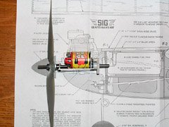
This Anthem dual-motor gearbox could be bolted directly to a glow engine mount, although I will probably install hardwood rails in the cowl sides instead.
Despite electric flight’s popularity however, the selection of available glow powered models is bigger, especially in the larger sizes. For the modeler wanting something the size of a .40 sized glow model, the selection is more limited. This leaves one with the option of either building from scratch, or converting a glow kit or ARF.
Planning
Glow kits are not designed with electric power in mind, and usually require extensive modifications if one wants to end up with a satisfactory electric model. Although it is tempting to dive into kit construction (or ARF modification), it’s worthwhile spending some time planning the conversion before setting to work. This is best done with a copy of the plan and instruction book in front of you, along with a red pencil (preferably an erasable one).
Motor Mounting
Most glow engines are installed either by bolting them to a firewall, or by bolting them to a pair of wooden rails inside the aircraft’s cowl. Most electric motors cannot be installed in this way.
The easiest mounting method for many motors is to bolt them to the back of a firewall, with the motor shaft protruding through. Doing this in a glow model will require moving the firewall forward, so that the motor shaft ends up in the same location as the intended glow engine’s shaft would have.
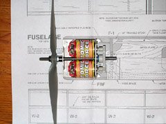
The Anthem gearbox fits exactly between the Sig Mid*Star 40‘s cowl sides. Very little work will be needed to replace the glow engine with electric power.
If the motor is large enough, it can be placed on the glow engine mounting rails, and held there with nylon cable ties or a steel cable clamp. Metal clamshell mounts are also available for some motors to facilitate attachment to a glow engine mount.
If using a geared or belt driven motor, the gearbox or belt-drive might have mounting holes allowing it to be bolted to a glow engine mount (the Modelair-Tech belt-drivers work well this way). It may be necessary to make a hole in the firewall for the motor to pass through.
There are many mounting methods available, and I discussed some of them in detail in the May 2002 issue of Sailplane & Electric Modeler (the former name of QuietFlyer magazine). Examine the plans carefully, and choose a mounting method suitable for the motor that will work in the model you are building.
Battery Installation
A glow model’s fuel tank remains in the plane, and only a tiny hole is required for a fuel filler tube (and a vent tube). An electric’s fuel is the battery pack, which is usually made removable so that one can change packs between flights instead of waiting for the pack to cool and then recharging it in the plane.
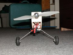
Front view of my reworked Fred’s Special. Cooling air enters the lower cowling, flows over the motor, over the battery, and through the fuselage.
This difference requires changes to the model which could compromise its structure, since a large opening is required to get the battery pack in and out. Since a battery pack is generally much heavier than the fuel tank it replaces, it will need to be placed further back than the fuel tank, often ending up in the under-wing area. The need for an extra opening can be eliminated by removing the wing to change batteries, but this is inconvenient at the field, so a hatch just in front of the wing is often desirable.
Refer to the November 2000 issue of Sailplane & Electric Modeler for descriptions of some battery mounting methods I’ve found practical. When choosing a method and designing the required modifications, be careful not to weaken the structure of the model (some weakening is acceptable due to the far lower vibration levels of an electric model).
Center of Gravity
An electric motor is approximately the same weight as an equivalent glow engine (with some variation either way), so the motor won’t affect the center of gravity (CG) much relative to the glow model. As mentioned above, the battery is much heavier, so care must be taken to locate it appropriately. This often results in other components, such as the receiver, servos, and receiver battery (if one is used) being relocated. All this must be taken into account so the completed model balances at the location indicated on the plans.
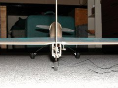
Rear view showing the open fuselage tail. The opening is rather small, but is adequate for the cooling requirements of this model.
Cooling Considerations
The only source of significant heat in a glow model is the engine, which is at the front of the model, with the cylinder head(s) protruding into the airflow (or with the airflow directed over the cylinders within a cowling). Electric power systems generate heat both in the motor, and in the battery pack. Both of these must receive adequate cooling to avoid overheating, especially in high-powered models.
Cooling the motor is fairly straightforward in most cases, since it’s in the same location a glow engine would be. Some additional ducting may be required to direct the air over the motor housing, since the source of motor heat is near its center, not in a protruding cylinder.
Battery cooling is a bit more problematic, since the battery is most often inside the model. This means that cooling air inlets and outlets are needed. To avoid excessive drag, these should smoothly direct the air into the fuselage, over the battery, and back out, without sharp corners or significant obstructions. As a rule of thumb, the outlet area should be about three times the inlet area.
Construction
When starting from a kit, there are many changes one can make during construction to optimize the model for electric power. The main goal is to build the model lighter to make up for the additional weight of an electric power system over the glow system it is replacing. Fortunately, an electric model does not need to be quite as strong as a glow model due to the much lower levels of vibration.
Lighter Wood
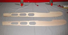
A plywood (top) and balsa (bottom) version of the Mid*Star 40 fuselage side. The kit-supplied plywood side weighs 2.9 oz. The balsa version weighs 0.8 oz. Replacing both sides, the top, and the bottom with balsa will save about half a pound.
The easiest way to save weight is to use lighter wood. Many .40 sized glow models have many plywood parts, some of which can be replaced with balsa wood. Candidates for replacement include fuselage sides and bulkheads (other than the ones under the wing leading and trailing edges, or the firewall).
Fuselage sides can be made out of stiff balsa of the same thickness as the plywood being replaced, with the grain running lengthwise. The area from the wing trailing edge to the nose should be reinforced with a doubler (an extra layer of balsa wood with the grain running vertically).
Balsa bulkhead replacements are best made from two layers of balsa wood laminated together (with CA, epoxy, or white glue), with the grains at right angles to one another.
If the model is already made of balsa wood, it might be possible to substitute lighter balsa for some parts, especially if the manufacturer hasn’t taken great care in selecting the lightest suitable balsa for each part.
Holes
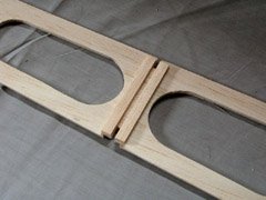
Vertical grain reinforcements between the holes in the fuselage sides will prevent splitting. Notice the smoothly rounded holes. Avoid square corners at all costs.
Compared to the air in which the model will be flying, a hole weighs nothing, so adding a hole will reduce the model’s weight by that of the material taken out of the hole. In the old days, most models were constructed from sticks, with sheet balsa used only for wing ribs. This produces a very light yet strong structure.
Although sheet balsa sides might be easier to construct, much of the material serves no useful purpose. Cutting significant holes into the sheeting can substantially reduce the weight. The one thing to keep in mind however is that balsa splits easily along its grain. When that grain runs the entire length of the fuselage, it’s usually strong enough to not require reinforcement (which is another reason sheet balsa sides are popular). When holes are added, it’s a good idea to run some vertical grain reinforcements between the holes.
One thing to keep in mind with holes is that stresses tend to concentrate in corners. All holes should have rounded corners, of at least a quarter inch radius. This makes covering easier too, since iron-on coverings tend to bunch up inside square corners.
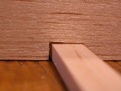
A poorly fitting rib-to-spar joint is not very strong. Poor parts fit is common in some kits (but not in the Mid*Star 40 kit from the previous photos).
Minimize Glue
With cyanoacrylate adhesives (CA), excessive use of glue is less of a problem than it used to be since it’s easy to apply CA sparingly. If using traditional adhesives, such as white glue or epoxy on the other hand, it isn’t hard to use too much. The strongest glue joint is one where the parts fit together well, and there is just a very thin layer of glue between them. A sloppy joint filled with glue will not be as strong, and will be much heavier.
It is possible to use too much glue even with CA. Properly fitting parts can be glued with Thin CA. If the parts fit reasonably well, but not perfectly, Medium CA will produce a satisfactory joint. There’s really no excuse to have joints loose enough to require Thick CA.
Lighter Covering
Models can be covered with many different materials, ranging from the traditional doped silk or silkspan, to modern iron-on heat-shrink coverings. Different coverings have different weights, but one can’t always compare the weights directly. Some aircraft have components designed to obtain some of their strength from the covering material, and substituting a lighter covering may not always be appropriate.
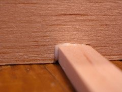
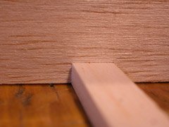
The glue needed to fill the gap both weakens the structure, and adds unnecessary weight, the enemy of electric flight.
In general, use the lightest covering you can find that is strong enough to serve its purpose on your model. Fabric-like iron-on coverings (like Solartex for example) are usually much heavier than polyester film coverings (such as Monokote), which in turn are heavier than polyethylene films (such as Solarfilm). The heavier coverings are also proportionally stronger.
There are some coverings, such as Micafilm or Fibafilm, which are both very strong, and very light. The two just mentioned are not self-adhesive, and require that the structure being covered first be painted with a heat-sensitive adhesive such as Sig Stix-It. This is more work, but results in a lighter model because the adhesive is only applied where it is needed, instead of on the entire back surface of the covering material.
Flying
A well thought out and implemented electric model can fly as well as its glow-powered counterpart. One should keep in mind however that most glow models are overpowered. Comparing a typical .40 sized trainer to a full-scale trainer aircraft (such as a Cessna 152), one notices drastically different performance. Most glow models can get off the ground in unrealistically short distances, and climb at steep angles.
Fly Realistically
For the beginner, this excess power can sometimes help get the plane out of a tight spot. On the other hand, too much power tends to reduce the need to actually learn to "fly" the plane. It becomes more like a video game than a model of an aircraft.
If your intent is to build a model that flies in a realistic, scale-like manner (even if it is not a scale model of a particular full-size aircraft), you may require less power than the manufacturer’s glow engine recommendation might suggest. A power system that delivers approximately 50 Watts per pound of ready-to-fly aircraft weight will already provide better than scale performance for an average civilian aircraft model.
Learn to fly the model "on the wing" instead of "on the prop". Use the throttle to adjust power to the task at hand instead of boring holes in the sky at full throttle.
This is not to say that one can’t model a high-performance plane with electric power, but only that not all planes need to be high-performance ones.
Related Articles
If you've found this article useful, you may also be interested in:
- Always Ready to Fly
- ARF Upgrades
- Scale Electric Airplane Design
- Model Airplane Electric Motor Mounting Methods
- Building and Installing Skis on Your R/C Plane
- Electric Aircraft Battery Mounting Methods

If you've found this article useful, consider leaving a donation in Stefan's memory to help support stefanv.com
Disclaimer: Although every effort has been made to ensure accuracy and reliability, the information on this web page is presented without warranty of any kind, and Stefan Vorkoetter assumes no liability for direct or consequential damages caused by its use. It is up to you, the reader, to determine the suitability of, and assume responsibility for, the use of this information. Links to Amazon.com merchandise are provided in association with Amazon.com. Links to eBay searches are provided in association with the eBay partner network.
Copyright: All materials on this web site, including the text, images, and mark-up, are Copyright © 2025 by Stefan Vorkoetter unless otherwise noted. All rights reserved. Unauthorized duplication prohibited. You may link to this site or pages within it, but you may not link directly to images on this site, and you may not copy any material from this site to another web site or other publication without express written permission. You may make copies for your own personal use.
David
August 28, 2008
Thanks for the article. You have provided a ton of info (construction) that has been observed over the years in a handy easy to follow text.