Retronome – A Versatile Analog Drum Machine for My Hammond Organ
May 25, 2009
When I purchased my 1962 Hammond M-111 organ back in 2008, it was a vast improvement over my mid-1970s Yamaha BK-20B. The drawbar controlled tonewheel sound, augmented by the warmth of the vacuum tube amplifier, made the Yamaha pale in comparison. There was one feature of the BK-20B that I sorely missed though, and that was the rhythm generator (also known as a drum machine). My sense of musical timing is terrible, but I wanted more than just a simple metronome, so I set out to design one that would be suitable for my Hammond spinet.
Twenty-first century drum machines use a microprocessor both to determine the rhythm, and play back recorded samples of actual instruments to generate the percussion sounds. In comparison, analog drum machines from the 1970s typically used transistor and diode based control logic for the rhythms, and analog transistor circuitry to produce percussion-like sounds. The rhythm generator in my Yamaha BK-20B could generate eight different rhythms, using a palette of seven synthesized percussion sounds (bass drum, snare, cymbal, hi-hat, high conga, low conga, and high bongo). More advanced drum machines such as the Roland TR-77 or Hammond AutoVari-64 could produce more percussion sounds, and more rhythms, along with a number of variations of each one.
The Design Process
In the process of designing Retronome, I studied the circuitry of several 1970s commercial offerings. One thing that virtually all had in common was a large diode array used as a read-only memory (ROM) to store multiple beat patterns for each instrument. Selecting a rhythm would cause one or more patterns and their corresponding instruments to be combined to produce the requested rhythm. I went through many possible designs based on these older methods, including one where the diode ROM was replaced by an EPROM chip, and another where there was a separate instrument-select switch for each point in a rhythm.
I eventually settled on a design half way in between, which I felt matched the Hammond organ philosophy very well. Much like a Hammond organ lets one combine individual harmonics to produce a sound (as opposed to the presets-only approach of other electronic organs), I devised a rhythm pattern generator that lets the organist select the individual percussion sequences separately. Thus one can add to or subtract from a rhythm just as one might adjust the drawbar settings to change the character of tone produced.
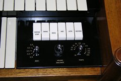
The final design has four rotary knobs and six tablet switches. The knobs are:
- Time signature: Selects 1/4, 2/4, 3/4, 4/4, or 6/8.
- Volume: Controls rhythm volume independent of the rest of the organ.
- Balance: Pans between “tone” instruments (bass drum, bongo, conga) and “noise” instruments (snare, cymbal, hi-hat).
- Tempo: Adjusts from 40 to 208 quarter-note beats per minute.
The tablet swtiches are:
- Basic rhythm on/off.
- Swing pattern.
- Rock pattern.
- Jazz pattern.
- Latin pattern.
- Western pattern.
The five position time signature switch together with the five patterns which can be selected in any combination can produce 144 different rhythms (not 160 because the Swing fill has no effect at the 1/4 setting).
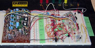
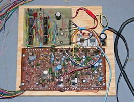
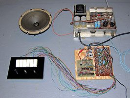
Breadboarded Retronome prototype. Yamaha percussion sound board is on the left. Rhythm pattern generator is on the right.
To avoid propriertary parts or custom programmed chips, I chose to implement all the rhythm pattern generating logic with TTL/LS integrated circuits. These are readily available and I happened to have all the chips I needed on hand.
With the rhythm logic design out of the way, the remaining issue was how to generate the actual percussion sounds. Most of the 1970s analog designs made use of hard-to-find inductors (coils), so I began designing op-amp based circuits requiring only resistors and capacitors. After several false starts, I realized that the percussion sound generation circuitry from my BK-20B was on its own circuit board, and that it would be possible to interface this with my rhythm logic, so I took the easy way out.
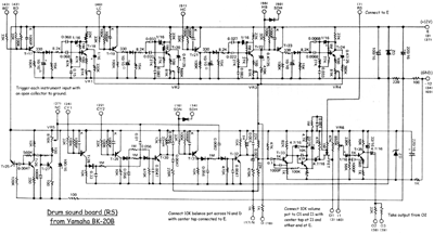
If you want to replicate this project, you’ll have to find a percussion sound board from a Yamaha organ. Fortunately that’s not hard to do since many of these old organs are being thrown out, given away, or sold very cheaply. Most of the Yamaha Electone series of analog organs used the same percussion board. For those who can’t find such a board and want to build one from scratch, I’ve included the schematic in this article.
The Rhythm Pattern Generator Circuit
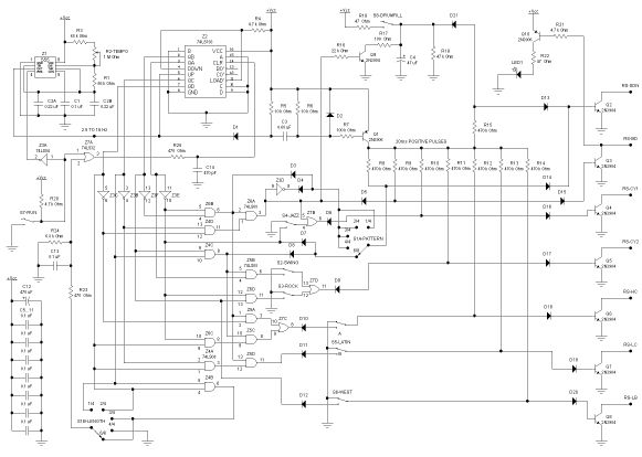
The rhythm pattern generator is implemented with a single 555 timer IC and six standard TTL/LS integrated circuits. Some diodes are used to provide additional logic.
Although this is probably the most complex circuit appearing on this web site, it is fairly straightforward if one examines it one piece at a time.
Clock Generator
Z1 is a 555 timer wired as an astable oscillator in the typical configuration. The only unusual feature is capacitors C2A and C2B, which are wired in parallel to achieve the desired capacitance. The goal was to achieve the standard metronome tempo range of 40 to 208 beats per minute. Since the rhythm pattern generator produces a beat every four clock pulses, the timer needs to produce 160 to 864 pulses per minute, corresponding to a frequency range of 2.67 to 14.4 Hz. By designing for a range of 2.5 to 16 Hz, the desired range will be achieved, even allowing for component tolerances.
Tempo control R2 should be a reverse logarithmic taper potentiometer if possible, so that the higher tempos aren’t all packed into the last few degrees of knob rotation.
The pulses from the timer will be about 17ms wide and active-low (the timer output is normally high, going low for the duration of the pulse).
Beat Counter
Moving to the right in the schematic, Z2 is a 74LS193 4-bit up-down counter. Z2 will increment its count at the end of each clock pulse from Z1. This means that during each clock pulse, Z2’s outputs are stable. Each quarter note beat corresponds to four counts of Z2, giving the rhythm pattern generator a resolution of sixteenth notes.
The reset input of Z2 is used to terminate the count early for 1/4, 2/4, 3/4, and 6/8 beats. For example, when using a 3/4 beat, Z2 only counts from 0 to 11 instead of the full 0 to 15 count range. It is also used to stop the counter completely when the rhythm is switched off.
Drum Trigger Pulses
The clock pulses from Z1 are also fed into a high-pass filter composed of D1, R5, C3, R6, and D2. This filter serves to produce slightly shorter pulses than those used to trigger the percussions sounds. These shorter pulses are over by the time that Z2 increments, so that the triggers are only produced when Z2’s outputs are stable (otherwise spurious percussion sounds could be produced).
The filtered pulses control transistor Q1, which inverts them and makes them available to each instrument’s trigger transistor via resistors R8 to R14. In the absence of the rhythm logic (to be described next), every instrument would be triggered on every sixteenth note.
Rhythm Logic
Returning to the left side of the schematic, Z3E, Z3F, Z3B, and Z3C produce inverted versions of the counter output bits QA through QD respectively. Z4 through Z6 are each 74LS08 quad 2-input AND gates that are used to decode these bits and inverted bits into rhythm patterns and control signals. Parts of Z7 (a 74LS32 quad 2-input OR gate), and diodes D3 to D12 are also used for decoding. Rather than describing the decoding logic in great detail, I’ll just present the following table describing the decoded sequences:
| Signal | Logic | Z2 Count (Hexadecimal) | Instrument | |||||||||||||||
|---|---|---|---|---|---|---|---|---|---|---|---|---|---|---|---|---|---|---|
| 0 | 1 | 2 | 3 | 4 | 5 | 6 | 7 | 8 | 9 | a | b | c | d | e | f | |||
| Basic 1 | D’C’B’A’ | X | Bass Drum | |||||||||||||||
| Basic 2 | DB’A’ + CB’A’ | X | X | X | Snare | |||||||||||||
| Basic 3 | CBA’ | X | X | |||||||||||||||
| Swing | CBA | X | X | Hi Hat | ||||||||||||||
| Rock | BA’ | X | X | X | X | |||||||||||||
| Jazz | A’ | X | X | X | X | X | X | X | X | Cymbal | ||||||||
| Latin 1 | DCBA’ + D’B’A’ | X | X | X | High Conga | |||||||||||||
| Latin 2 | DC’B’A’ | X | Low Conga | |||||||||||||||
| Western | B | X | X | X | X | X | X | X | X | High Bongo | ||||||||
| Reset 1 | C | X | X | X | X | X | X | X | X | |||||||||
| Reset 2 | D | X | X | X | X | X | X | X | X | |||||||||
| Reset 3 | DC | X | X | X | X | |||||||||||||
The Basic 1 sequence is always used when the rhythm pattern generator is running. It triggers the bass drum and cymbal during the zero count of Z2.
Rotary switch S1 is a 5-position two section rotary switch. Section S1A selects which basic snare pattern (Basic 2 or Basic 3) is used. S1B selects when to reset Z2 to produce the correct sequence length for the selected time signature (Reset 1 for 1/4, Reset 2 for 2/4, Reset 3 for 3/4 and 6/8, or no reset for 4/4).
Switches S2 through S6 determine whether the Swing, Rock, Jazz, Latin, and Western sequences are activated.
Instrument Triggers
Transistors Q2 to Q8 trigger the individual sounds on the Yamaha percussion sound board by briefly grounding the appropriate trigger input. The high level pulses from the collector of Q1 are applied to the bases of Q2 to Q8 unless the corresponding sequence control signal is low at the time, either because of the decoding logic, or because the corresponding switch is off (switched to ground).
The diodes at the input to each trigger transistor ensure that no current flows into the transistor’s base when the output is low. This is necessary because the low level of the trigger signal lines is about 1.4V (due to the combined effect of a 0.7V TTL low output and diodes D3 to D12). This is higher than the transistors’ 0.7V base-emitter drop. The additional diodes effectively increase the base-emitter drop to 1.4V.
Rhythm On/Off
Switch S7 controls whether the rhythm pattern generator is running or halted. When off, the input of Z3A is pulled high through R20, making its output low and disabling Z1. Similarly, one input of Z7A is high, making the output high and forcing Z2 to a zero count. Turning S7 on lets Z1 start running and Z2 begin counting from zero.
Visual Downbeat Indicator
Transistor Q1 drives downbeat indicator LED1. The LED flash is very short (about 10ms), so R22 is chosen to drive the LED at 50mA to produce a bright flash. This is higher than the continuous current limit of most LEDs, but within the pulse current limit.
Drum Fill
This feature was added as an afterthought. During prototyping, I discovered that disconnecting the base of a trigger transistor from its control signal would result in a continuous sequence of whatever sound that transistor was responsible for triggering. This was because there was no longer anything inhibiting the trigger pulses from Q1.
Briefly closing S8 rapidly charges C4 through R18. This allows a trigger pulse to pass through R15 and D13 into snare trigger transistor Q2, resulting in a snare hit on every pulse. Transistor Q9 discharges C4 when counter Z2 is reset, ending the drum fill sequence at the next downbeat. Resistor R19 inhibits charging of C4 by the trigger pulses themselves.
Percussion Sound Board
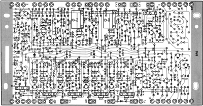
As already mentioned, the percussion sound board was taken from a Yamaha BK-20B organ. The same sound board was used in the entire BK-20 series, and many other 1970s Yamaha analog electronic organs. This board, marked “RS”, contains the individual percussion sound generators, balance circuitry, volume control circuitry, and a pre-amplifier. The capacitively coupled output has a level at maximum volume of about 1V peak-to-peak into 47kΩ. The board also contains some parts of the Yamaha’s rhythm tempo control circuitry, but this is not used in the Retronome project.
For those who want to build this project and can’t obtain a Yamaha sound board, I’ve reproduced the schematic and circuit layout below (the unused tempo control has been omitted from the schematic). It should be possible to reproduce this circuit using modern transistors.
The sound board was designed to operate on negative 12VDC. At first I feared that interfacing it to my rhythm pattern generator would be a challenge, until I realized that I could operate it from a positive 12VDC supply by connecting it to the board’s “E” (earth) terminal, and the power supply’s ground terminal to the board’s “-12V” terminal. This allowed the rhythm pattern generator’s open-collector trigger transistors to directly drive the board’s instrument trigger inputs.
Power Supply
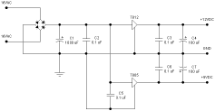
The TTL-based rhythm pattern generator circuit operates on a 5VDC while the sound board requires 12VDC. I constructed a simple linear power supply using a rectifier, filter capacitors, and 7805 and 7812 regulators, all powered by a 16VAC wall-wart. Total power consumption is under 200mA, so almost any 16 to 18VAC source will do (it will even work from 18VDC).
I decided on the component layout during construction, so I did not design a detailed stripboard or PCB layout for the power supply. All I have to show here is the schematic.
Construction
Unlike most other projects on this web site, I will not provide detailed construction instructions here. This is an experimenter’s project, so I’ll just briefly describe what I did and leave the details as an exercise for the reader.
Rhythm, Sound, and Power Supply Boards
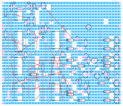
After first prototyping the design on a breadboard, I chose to construct the rhythm pattern generator logic on a piece of pre-etched stripboard, the layout of which is as follows (shown from the top of the board):
After wiring the rhythm board, I began the tedious process of connecting wires to it to reach the switches and tempo control potentiometer on the control panel, and the trigger inputs on the percussion sound board. I also connected wires to the sound board for the volume and balance potentiometers.
I constructed the power supply on a separate smaller piece of stripboard, deciding where to place the components and cut traces as I went along.
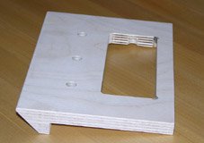
I mounted the rhythm pattern generator, power supply, and sound board on a plywood base plate cut to fit on the inside right hand end of the organ, above the vibrato scanner. The notch in the board is to clear the rear top rail of the organ.
Front Panel and Controls
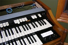
Since I built Retronome to use with my Hammond M-111 organ, I decided to integrate it into the organ. The M-100 series has a blank cheek block panel on each side of the lower manual. The one on the left is larger, but the right hand one was large enough to incorporate all the controls (and I have future plans for the left one).
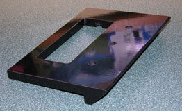
I considered cutting up the existing plastic (Bakelite?) cheek block to accomodate the controls, but eventually decided to build a new one from scratch instead. I was inspired by the panels from the Yamaha, which I originally thought were metal or plastic, but turned out to be plywood with an extremely fine finish. Using the existing plastic panel as a guide, I constructed a new one out of 12mm (1/2″) baltic birch plywood.
The controls consist of six on/off switches, one rotary switch, and three potentiometers. For the switches, I used a block of tablet switches from the BK-20B, spray painted an ivory colour to match the existing switches of the Hammond. The Yamaha organ also yielded a pair of concentric potentiometers to control the volume and balance. The time signature selector was implemented using a widely available 2P6T rotary switch, using only five of the positions.
The one tricky control was the tempo control. Because it linearly controls the time interval between clock pulses, it controls the rate in a reciprocal manner. Using a linear potentiometer, the higher tempos (100 to 208 bpm) ended up in the last 10% of the potentiometer’s rotation. I determined that what I needed was a 1MΩ reverse-logarithmic taper potentiometer, which took some time to find. I eventually found one at Weber Speakers (it had a switch however, meaning that about 30° of the rotation provided no change in resistance).
Testing and Calibration
After completing construction, I temporarily wired the panel to the circuitry for testing. I connected the output from the percussion sound generator to a spare amplifier (also taken from the Yamaha organ) and speaker. Everything more or less worked, except that I noticed a propensity for the circuit to skip a beat every now and then. I eventually narrowed the problem down to noise brought on by the long control panel leads. That was when I added the delay circuits consisting of R23/R24/C13 and R25/C14 to the design. Fortunately these were easy to retrofit onto the rhythm pattern generator board.
Once the circuit was working properly, I determined the exact tempo at each extreme of the tempo control (by recording them to a WAV file and measuring it in Audacity). I then disconnected the tempo potentiometer from the circuit, connected it to a resistance meter, and marked the panel at the settings where the resistance matched the values I computed for various tempos approximately evenly spaced around the dial.
I labeled the panel using a Brother P-touch label printer, using gold-on-black tape to label the panel for the rotary controls, and black-on-clear tape to label the tablet switches. The panel was then finished with a coat of semigloss varnish.
Installation in the Organ
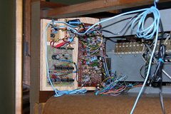
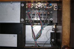
To install Retronome in the organ, I first had to disconnect the control panel. I installed the plywood board containing the rhythm pattern generator, sound board, and power supply on the inside right hand wall of the organ, just above the vibrato scanner. The wiring to the control panel was passed through the organ to the front, at which point I could reconnect it to the panel.
The Hammond M-100 series of organs has an RCA input jack on the expression pedal housing intended for connecting a record player, tape player, or 1960s phonograph (although it is labeled “RADIO/PHONO”, it does not accept a “modern” RIAA phono-level input — it expects a 0.5V audio signal). This input is compatible with the output level of the Yamaha percussion sound board, so I simply connected it there with a length of shielded cable.
There are two drawbacks to this approach:
-
The amplifiers in the Hammond spinet models have a very poor high frequency response. This was done intentionally to minimize keyclick. Unfortunately this also attenuates the cymbal and snare sounds, which have significant high-frequency content.
-
I’ve modified my Hammond to have a built in rotating Leslie-like speaker, and the percussion instruments sound strange when played through this speaker, especially at the tremolo setting. I’ve decided to live with this until I’ve completed some other changes I have in the pipeline.
To accomodate the rhythm generator’s power supply wall-wart, I installed an electrical outlet inside the organ, controlled by the organ’s power (Run) switch.
Planned Changes
In the not-too-distant future, I plan to build a pair of external multi-speaker tone cabinets for the organ into a wall-to-wall window seat and bookcase, with their own amplifier. At that time, I will connect the percussion sound output, and a line-level output from the organ, into a two-channel mixer which will feed the external amplifier. This means that the rhythm sounds will play only through the external speakers and will avoid the problems of playing them through the organ’s treble-attenuating amplifier and the rotating speaker.
[October 2009 Update: The window seat bookcase project has now been completed. You can read about it in this article.]
Audio Samples
If you’ve read this far, you’re probably wondering what this thing sounds like. The following samples were all recorded with the time signature set to 4/4 and the balance control centered. Each sample consists of the basic bass-and-snare rhythm at 100 bpm. The second through sixth samples each contain one of the additional patterns as well. The last sample contains the basic rhythm and three patterns. Each sample is exactly one bar in length, so you can loop it until you get tired of it.
- Basic
- Basic with Swing Pattern
- Basic with Rock Pattern
- Basic with Jazz Pattern
- Basic with Latin Pattern
- Basic with Western Pattern
- Complex Rhythm (Basic, Swing, Rock, and Latin)
These recordings were made by connecting the output signal of the sound board directly to the line input of a PC sound card.
Related Articles
If you've found this article useful, you may also be interested in:
- MusicRack – A Digital Sheet Music Display System
- Building a Musical Sunrise Quartz Alarm Clock
- Chord EGG 2015: Remaking a PAiA Classic
- Oh, the Noise! Noise! Noise! Noise! – Stringz’n’Thingz Revisited
- Rejuvenating and Expanding a PAiA 1550 Stringz’n’Thingz Synthesizer
- Rebuilding a Hammond AO-29 Amplifier from the Ground Up
- Hammond Organ Tonewheel Generator Capacitor Replacement and Calibration
- Overhauling the AO-29 Amplifier in the Hammond M-100 Series
- Window Seat Bookcase Tone Cabinets for a Hammond Organ
- Overhauling and Improving the Hammond M-100 Series Vibrato System
- Adding a Rotary Speaker to a Hammond M-111 Organ

If you've found this article useful, consider leaving a donation in Stefan's memory to help support stefanv.com
Disclaimer: Although every effort has been made to ensure accuracy and reliability, the information on this web page is presented without warranty of any kind, and Stefan Vorkoetter assumes no liability for direct or consequential damages caused by its use. It is up to you, the reader, to determine the suitability of, and assume responsibility for, the use of this information. Links to Amazon.com merchandise are provided in association with Amazon.com. Links to eBay searches are provided in association with the eBay partner network.
Copyright: All materials on this web site, including the text, images, and mark-up, are Copyright © 2025 by Stefan Vorkoetter unless otherwise noted. All rights reserved. Unauthorized duplication prohibited. You may link to this site or pages within it, but you may not link directly to images on this site, and you may not copy any material from this site to another web site or other publication without express written permission. You may make copies for your own personal use.
guillermo
June 24, 2009
hi mannnnn! you are a genious!! !:) great job
Anonymous
September 23, 2009
What, no SILENT/SOUND switch! :o)
israel
May 19, 2010
hi i do have a problem with my yamaha yc 30 electone organ aparents the problem be the power suplyer i,change already a part says 10dc 1r for a adjustable voltage regulator LM 317T the ones are in the redio shack store and the organ start to make good sound with a little noise and in a few minutes one of the capacitors is over heating and i have to turn the organ of and i like to now from you if i,make mistake when i change the part for the another may be,thath was the problem,?thanks you can call,me if you wanth thanks again ,,
Colin
March 21, 2012
Hi Stefan, I really like the Leslie speaker sound, but can understand why it might clash with the rhythm output. You are probably considering a separate amp and fixed speaker for the rhythm alone – that’s if you have any room left in your organ – you might have to consider a satellite speaker/amp for this. You did a lovely job modifying and adding the rhythm unit, the hybrid design was a nice job, and the physical modification looks just like a factory job, your work is very nice. We share quite a few interests, so your whole web site has many interesting things!
Stefan Vorkoetter
March 21, 2012
Hi Colin, since the time I wrote this article, I’ve fed the rhythm unit output to my external non-Leslie tone cabinets (see http://www.stefanv.com/electronics/hammond_window_seat.html for details). It works quite nicely, since a real percussionist wouldn’t be playing from inside the organ anyway.
Andrei
September 04, 2012
Hi there !
I have the oportunity to buy a working yamaha bk-20b organ very very cheap (about 50euro) and wanted to ask you some stuff about it as I can’t find any information on it on the web. I’m interested in using it’s sound for house music. Is it possible to connect it to a PC and using it with modern software ? I know this is a long shot as it is very very old. Anyway, thought i might as well ask. Thanks
Stefan Vorkoetter
September 04, 2012
Andrei, a BK-20 is a purely analog organ. It does have a line output, so with the appropriate adapter, you can feed that into the line input of a PC’s sound card.
Andrew Ward
October 20, 2012
Hi Stefan
Good work and a great article. I find this one and the one on the revolving speaker very useful because I have 3 old Yamahas of various models (they are available for next to nothing on ebay these days – in fact most don’t sell) and I’m trying to restore them as best I can. Electrolytics and transistors are failing faster than I can replace them! Your articles are a great source of information on organs in general and specifically the Yamaha RS board and revolving speaker. However I still have no real option but to trace the circuits and work through painstakingly with a scope to find and fix the numerous faults. Most of the audio circuits are kind of straightforward but I still have to tackle the motor drive circuit on one of the revolving speakers. I’ll replace the electrolytics and cross my fingers!
Regarding this project itself I would probably use something like the ATMega8 to drive the RS board as an alternative to TTL. I might have to do this if the rhythm pattern generator fails on one of the Yamaha, they would probably be difficult to fault-find.
David
July 30, 2013
Hello, Ive got an identical sound board to play with.
I was wondering if you had any tips to make the sounds more adjustable?
There is obviously the pots on the board, but the circuits for BD congas and Tom for look almost identical, so replacing the resistors with different values for pots of a large range or something might be a good idea?
And also, the sounds are triggered by S-trig correct?
Mike p
April 25, 2014
I’m working with the same RS board from a yamaha dk40 right now. To the guy asking about replacing resistors on each drum section, I’ve done it and on the kick it’s amazing, took out 4 and put some different value pots in there to tune it and control decay and it can go subsonic like an 808. Did other drums as well for some cool results, feedback, tuning, decay don’t know what I’m doing really just experimenting with a free organ so figured nothing to lose! Can take pix if anyone’s interested
Stefan Vorkoetter
April 25, 2014
Mike, I’d be very interested in seeing pictures. If you e-mail them to me, I’ll add them as an addendum to this article.
mike p
April 25, 2014
Hi Stefan – I will do that. I just soldered a bunch of leads coming off the bottom of the RS board and out to the pots – it’s kind of a big mess at the moment, but I’ll try to get a clear picture for you. This is my first venture in circuit modification and I’m encouraged to do more due to this going so well. I plan to mount the RS board in an old Tapco mixer case (which happened to be the donor of many of the pots) along with the pattern generator from the organ, which I need to track down. I found your site trying to figure out the power supply, but maybe a 12v DC wall wart may work??? I can possibly get you a sound sample as well. Don’t know if you’re interested in synthesizers or not but a lot of the Yamaha organs from 1977-1982 (models with “Upper Orchestra Presets”) have CS series filter and adsr circuits inside and just need pots subbed in the right places to make synths out of them. I started on this drum machine as practice for that project I would like to tackle on an E70.
Mike p
July 05, 2014
Hi Stefan
Sorry I never got back to you on this. Had a few problems unrelated to the mod though. I actually fried something on the RS board due to my lack of knowledge…didn’t realize the ears that hold the board in the rack are tied to ground and -12v, mounted them to the Tapco metal face plate and shorted it all out. Too bad because I had it working out of the organ off a 12v wall wart. Currently trying to see if an RS board from a D80 Yamaha will work with the DK pattern cards. I’ll keep you posted.
Kurt Kabica
December 23, 2014
Hi Stefan Thank you very much for this wonderful piece I build one ,but I am waiting to try it out until I can build the voices for It.. have built some proto type boards using simpler(parts wise) op-amp bridged-T oscillators like : mikeydelp.com/news/anatomy-of-a-drum-machine.html used on his project they need around 5 volt square wave to make them thump. It seams like goofy question how would I tie-in your design in to these type of noise makers , would the transistors at the out end of your design, make nice a square wave to excite this type of oscillator ? I know its been years since you wrote this article. your ideas would be great Thank you!! best regards Kurt
Stefan Vorkoetter
December 23, 2014
I’m unable to look at the page you’re referring to, so I can’t really comment on what would be required to trigger his voices. Assuming they trigger on a 5V rising edge, then you can probably trigger them directly from the diodes that drive the transistors in my circuit (and omit the transistors).
Casey Johnson
January 21, 2018
Hey,
Love your website, especially the hammond and drum machine stuff.
I was trying to trouble shoot the rhythm ace (model number ?) analog drum machine that came with my hammond T211 organ. Quite similar to this project you described.
I am getting a significant 60 hum (measured with a scope) from the audio output. Checked the dc power supply, which looked fine. The hum changed with proximity of my body to the cable connecting the controller to the tone generator (the many wired cable). It makes the hum any time the unit is on sound rather than silent mode regardless of the rhythm selected. Varies with volume knob. I was thinking originally a grounding problem or proximity to some mains lines in the organ.
Removed the unit from the organ and still got it, noise got louder with my hand near or around the multi wire cable. Thinking this is due to an issue with this cable – ie changing capacitance orinductance due to the mains wiring sending electromagnetic waves into the air? The long low voltage signal wires act like an antenna, changing the capacitance of the wires? Thinking of shortening the cable significantly might do it. Or am I missing something?
Thanks,
Casey
Stefan Vorkoetter
January 21, 2018
Your original hunch of a bad ground is far more likely than the complicated scenario you have outlined. Also, are you sure the DC supply is clean? It’s probably quite old, and needs its electrolytic capacitors replaced.
sebtux74
October 04, 2018
Dear Stefan,
Your blue stripboard layout is very nice. What is the software name?
thank you
Stefan Vorkoetter
October 04, 2018
It doesn’t really have a name. It is a keyboard-driven circuit board layout program I wrote years ago, originally for DOS, and later ported to Windows. I use it for designing printed circuit boards too, not just stripboard layouts. The colour was actually added afterward in Photoshop. 🙂