Overhauling the AO-29 Amplifier in the Hammond M-100 Series
December 23, 2009
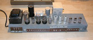
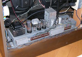
AO-29 amplifier from my 1962 Hammond M-111, on the workbench, with "can" capacitors clearly visible.
Well built vintage electronic circuitry can last a very long time, as evidenced by the number of Hammond organs that are still working, some from as far back as the 1930s. Hammond’s engineers designed their vacuum tube (valve) amplifiers conservatively, putting minimal stress on the components. All but one of the tubes in my 1962 Hammond M-111 is original and I have no intention of replacing them unless one fails.
However, one type of component that is prone to wearing out, regardless of how little or how much a piece of equipment was used, is the electrolytic capacitor. A capacitor consists of two electrodes separated by an insulating material (dielectric). Capacitors store electric charges and block the flow of direct current through them while allowing alternating current to pass. An electrolytic capacitor is one where the insulating layer is porous and impregnated with an electrolyte solution (somewhat like a battery).
The characteristics of this electrolyte change over time, potentially affecting the capacitance. There is also a risk of short-circuits forming, which can result in the capacitor leaking or exploding. The corrosive electrolyte can damage wiring or the chassis, but more importantly, the sudden failure of the capacitor can cause damage to much more expensive components such as the vacuum tubes that are relying on it to do its job.
Capacitors in the M-100 Series AO-29 Amplifier
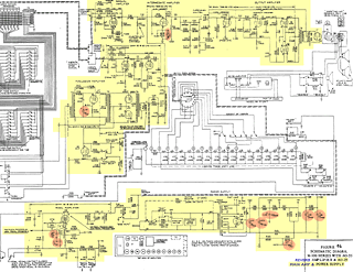
Part of the schematic diagram of the Hammond M-100 series, with the AO-29 amplifier and its electrolytic capacitors highlighted.
In the Hammond model AO-29 amplifier, electrolytic capacitors are only used for filtering. Large capacitors are used to filter the pulsating direct current from the rectifier into something smooth enough to operate the rest of the amplifier. A few other electrolytics are used throughout the amplifier to provide local filtering. Since aging electrolytic capacitors tend to increase in capacitance, they become better filters, so that alone would not justify replacing them. However, minimizing the risk of damage to the tubes, especially the expensive 5U4 rectifier, makes capacitor replacement worthwhile.
There are a total of ten electrolytic capacitors in the AO-29 amplifier. Two of them are on top of the chassis in the large black “can” to the left of the intermediate transformer (when viewed from the back of the organ), four more are in the silver can to the right of transformer, three are on the wiring boards inside the chassis, and one is wired directly to a tube socket.
It is possible to purchase replacement can capacitors from sources such as Tonewheel General Hospital but these are relatively expensive. I opted to replace the cans with separate electrolytic capacitors of the appropriate values instead. The following table summarizes all the capacitors to be replaced:
| Designation | Original Location | Original Value | Replacement Value |
|---|---|---|---|
| C14 | Silver Can | 30µF 25V | 33µF 50V |
| C30 | Wiring Board | 25µF 25V | 27µF 50V |
| C62 | Black Can | 50µF 450V | 47µF 450V |
| C62A | Black Can | 50µF 450V | 47µF 450V |
| C63 | Silver Can | 20µF 300V | 22µF 450V |
| C64 | Wiring Board | 25µF 25V | 27µF 50V |
| C65 | Silver Can | 40µF 400V | 47µF 450V |
| C66 | Silver Can | 20µF 400V | 22µF 450V |
| C67 | Wiring Board | 100µF 3V | 100µF 6.3V |
| C70 | Tube Socket | 3µF 50V | 3.3µF 50V |
I ordered the replacement capacitors from Digi-Key (along with new capacitors to replace the aging wax-paper ones in the vibrato line box and
Removing the Amplifier
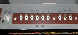
Although it is theoretically possible to replace the capacitors with the amplifier still in the organ, it would have been extremely awkward, so the first step was to remove it from the organ. This required unsoldering a row of connections along the back of the amplifier, including the AC power connections enclosed by a metal cover and some shieled audio signal connections under another cover. To ensure I’d be able to reconnect everything properly afterward, I took several close-up photos of all the connections before starting.
Once all the connections were unsoldered and neatly tucked out of the way, I loosened the screw holding holding the expression pedal lever on the shaft of the expression pedal capacitor (inside the silver box on top of the amplifier) and slid the end of the lever off of the shaft.
Next I undid the four bolts that hold the amplifier chassis to the floor of the organ and carefully lifted the amplifier out. I debated whether I should remove the tubes before or after extricating the amplifier, and decided to wait until the amp was on the workbench. I was afraid that a hard-to-remove tube might let go suddenly and that I would smash it against something in the organ.
After carrying the amplifier to my workbench, I carefully removed each tube, placing them in consecutive compartments of an egg carton. I inspected each tube as I removed it to make sure I could still read its markings in case I managed to mix them up in the carton. Once all the tubes were out, I set them aside, out of harm’s way.
Replacing the Can Capacitors
Before beginning, make sure that any high voltages stored in the capacitors have been discharged. Using a clip lead, connect one end of a 1kΩ resistor to the chassis. Then using another clip lead, touch the other end to each capacitor positive terminal for a few seconds.
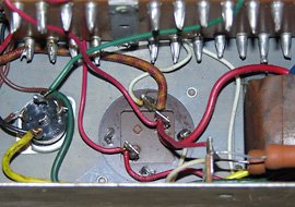
The first step in replacing the cans was once again to photograph everything in great detail. In addition to the photos, I drew a diagram indicating all the connections and where they lead to. Finally, I marked each wire to identify the terminal it was connected to. There are a lot of wires connected to the capacitor terminals and many of them are the same colour, so I did everything possible to avoid a later mix-up.
The individual capacitors within each can are identified on the side of the can with a symbol for each one (e.g. triangle, square, semicircle), and the contacts on the bottom of the can are marked with the same symbols. There is one solder lug for the positive terminal of each capacitor, whereas the negative terminals of all the capacitors in the can are connected together and to the can itself. In other words, the four twist-tabs that serve to hold the can to the chassis are also negative terminals for all the capacitors.
The Black Can (C62 and C62A)
The following steps describe the work done to replace the black can (containing two 50µF 450V capacitors, C62 and C62A).
Removing the Can
I unsoldered the wires using a 45W soldering iron (not a soldering gun) and a plunger-type solder pump. As I heated up each solder lug, I used the pump to suck away most of the solder. I used desoldering braid to wick up most of the remaining solder. With the solder gone, it was possible to unwrap the wire from each lug and then heat it up once more to pull the wires out.
Once all the wires were off, I straightened out the twist-tabs holding the can to the chassis and cleanly removed it. After removing the black can, there was still the phenolic socket to remove. I did this by drilling out the rivets with a 1/8″ drill bit from the top side of the chassis.
Mounting the Replacment Capacitors
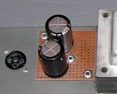
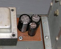
To mount the individual replacement capacitors, I cut a piece of phenolic perfboard 1.7″ x 1.7″. I drilled out three of the holes to 1/8″ diameter. Two of these corresponded with the existing rivet holes in the chassis and the third was approximately in the centre of the perfboard.
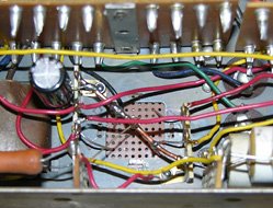
Using 1/8″ steel pop rivets, I riveted the board to the chassis and then riveted a 4-position terminal strip to the underside of the perfboard. I connected the two centre lugs together to act as negative terminal for both capacitors. The two outer lugs were then for the positive terminals of each capacitor. The capacitors were installed from the top side of the board, paying careful attention to polarity and keeping the leads away from the chassis edges, and their leads were passed through the holes in the appropriate lugs underneath.
With the capacitors in place, all the wires were routed to their appropriate lugs. After carefully checking the wiring against the original photos, drawings, and the markings on the wires themselves, everything was resoldered. The end result was quite neat (by 1960s point-to-point wiring standards).
The Silver Can (C14, C63, C65, and C66)
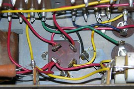
The silver can differs from the black one in two ways: it contains four capacitors instead of only two, and the negative terminal solder lugs are fastened directly to the chassis instead of to an insulated socket. Since there are four capacitors, I needed at least five solder lugs (at least one negative and four positive terminals). Instead of a single 5-position terminal strip, I used two 3-position strips with the mounting lug at one end of each. I fastened one strip with each rivet holding the perfboard in place, which served to connect the end lug to the chassis.
I cut a short length of 14 gauge solid copper wire and passed it through these two end lugs, effectively forming one long negative buss passing diagonally under the perfboard. Three of the four capacitors were then installed on top of the perfboard with their negative leads connected to the copper wire and their positive leads connected to individual lugs. No matter how I arranged things, I was unable to fit all four capacitors above the chassis, so I installed one of the 22µF capacitors (C66) underneath, connecting it directly to the terminal strip lugs.
With the capacitors in place, I reattached the wires to the appropriate solder lugs and then soldered everything.
Replacing the Other Capacitors (C30, C64, C67, and C70)
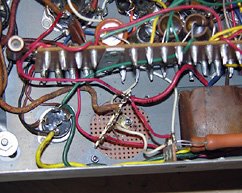
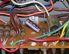
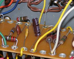
The two 25µF 25V electrolytic capacitors, C30 and C64, are near the two ends of the wiring board. Before removing the old ones, I marked the bottom of the board with the polarity so I’d be sure to install the replacements the right way around.
Removing the old capacitors was easy, just requiring a few seconds of the soldering iron on the underside of each turret to melt all the solder within, at which point the capacitor’s lead could be pulled out. Installing the new capacitors was the same process in reverse: melt the solder in the turrets and push the leads in.
For some reason, I forgot to replace C67 and C70, which I did not realize until I began to write this article long after reinstalling the amplifier in the organ. Since these capacitors are not riveted in, thus just requiring unsoldering and resoldering, I can probably replace them without removing the amplifier. Fortunately, neither of these capacitors are as critical as the power supply capacitors, and a failure would not likely damage any other components. Both are used as filters in the bass pedal circuit.
Other Maintenance
While the amplifier was readily accessible, I decided it would be a good idea to do some general maintenance:
-
The chassis was covered with what looked like dust but which was almost impossible to wipe off. I suspect it was dust, held in place by a thin layer of Hammond tonewheel oil that had accumulated over the decades. I removed it using rubbing alchol, a rag, and a toothbrush.
-
The chassis has labels stamped into the metal next to each tube socket (identifying the tube type) and external connection (giving the wire colour and designation). These were almost illegible in most lighting conditions, so I darkened them with a black Sharpie® permanent marker, followed by a wiping with an alcohol dampened rag to remove the marker everywhere except within the stamped letters.
-
Before embarking on this exercise, I was experiencing a problem with crackling noises emanating from the speaker when the organ was played at high volume. Consulting with the folks on The Organ Forum suggested that it might have been a tube moving in a dirty tube socket, causing an intermittent connection, so I thoroughly cleaned all the sockets using DeOxit D-5 spray.
-
I cleaned up all the external connection terminals using the solder pump and desoldering braid to remove all the excess solder and rosin.
-
I had briefly looked into the amplifier when I first purchased the organ in 2008 and found one capacitor (C70) that had become disconnected from a tube socket terminal (which is how I know that a failure of C70 won’t cause any damage). With the amplifier on the bench, I gave it a more thorough inspection with a magnifying glass to check for other broken connections.
Reinstalling the Amplifier
With all the capacitors replaced (except C67 and C70), I gave everything one more check, comparing my rewiring against the original photos and drawings, and also the schematics from the service manual for good measure. Everything looked good, so I carried the amplifier back upstairs to reinstall it into the organ.
I first bolted it back in place and then started reconnecting the wires from right to left. After everything was soldered to my satisfaction, I replaced the two metal covers (one for the AC line voltage and one for the shielded audio connections) and then reinstalled the tubes. To keep things neat, I also wrapped the bundle of wires leading down to the amplifier with electrical tape.
One last check and then I started the organ. After letting it warm up for 20 seconds or so, I tentatively pressed a key and was rewared with a note from the speakers. A thorough check showed that everything was (still) working, except the expression pedal. I quickly realized I forgot to reattach the pedal arm to the side of the dog house.
Uh-Oh!
With the expression pedal reconnected, I sat down to play something. Part way through the piece, I heard what sounded like a capacitor going up in smoke (a sort of whooshing sound). Strangely, there was no smoke and no smell, and everything still worked. I looked behind the organ and everything looked fine. I continued playing and the whooshing came and went. Usually, changing anything (like turning the internal rotary speaker on or off) would make the sound disappear for a while, but then it would return.
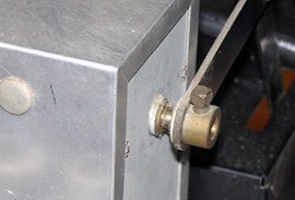
The expression control lever was not properly seated on the shaft, injecting white noise into the amplifier.
I would have been concerned that something I did had caused this problem, but it had happened to me once before. I did some more experimentation and discovered that if I pushed the expression pedal all the way, there was a clanking noise and the organ got very quiet. I came to the realization that the plates of the variable capacitor that controls the volume were hitting the wall of the dog house, thus shorting the signal to ground. I took another look at the expression lever and shaft and noticed that the lever end wasn’t seated all the way onto the shaft. I loosened the set screw, pushed the lever further onto the shaft, and retightened the screw. After that, the expression pedal worked properly over its full range and the whooshing was gone. My theory is that the loose attachment of dissimilar metals created what amounted to a diode junction, and that this was producing white noise that was getting into the amplifier.
Conclusion
Did it sound any different when I was done? No, but I didn’t expect it to. All of the old capacitors still measured very close to their stated values, so they were still working as designed. Unlike
Related Articles
If you've found this article useful, you may also be interested in:
- Rebuilding a Hammond AO-29 Amplifier from the Ground Up
- Hammond Organ Tonewheel Generator Capacitor Replacement and Calibration
- Window Seat Bookcase Tone Cabinets for a Hammond Organ
- Retronome – A Versatile Analog Drum Machine for My Hammond Organ
- Overhauling and Improving the Hammond M-100 Series Vibrato System
- Adding a Rotary Speaker to a Hammond M-111 Organ

If you've found this article useful, consider leaving a donation in Stefan's memory to help support stefanv.com
Disclaimer: Although every effort has been made to ensure accuracy and reliability, the information on this web page is presented without warranty of any kind, and Stefan Vorkoetter assumes no liability for direct or consequential damages caused by its use. It is up to you, the reader, to determine the suitability of, and assume responsibility for, the use of this information. Links to Amazon.com merchandise are provided in association with Amazon.com. Links to eBay searches are provided in association with the eBay partner network.
Copyright: All materials on this web site, including the text, images, and mark-up, are Copyright © 2025 by Stefan Vorkoetter unless otherwise noted. All rights reserved. Unauthorized duplication prohibited. You may link to this site or pages within it, but you may not link directly to images on this site, and you may not copy any material from this site to another web site or other publication without express written permission. You may make copies for your own personal use.
Soeren Poulsen
December 25, 2009
Very nice article, easy readable, and understandable, and the photos are great. I think I would have used glass-fiber pcb boards, having made pads with a permanent ink pen, ant etched it, but that is just a matter of taste. Good work. Thanks for sharing. Soeren
Fernando
September 25, 2012
very interesting article, thanks for sharing your experience and knowledge
Daniel C
February 10, 2013
Hi,
do you think AO-29 tube amp suite for HI-FI?
cheers
Daniel
Stefan Vorkoetter
February 10, 2013
Daniel, the AO-29 wouldn’t make a very good Hi-Fi amp at all. It’s frequency response drops off rapidly after about 5kHz, and has very high levels of distortion. If you want a good Hi-Fi amp, get a modern solid-state one (almost any modern solid-state amp, even the cheapest, is a far better Hi-Fi amp than any tube amp ever built). And of course, the AO-29 isn’t stereo either.
Phil VL
February 12, 2014
That’s a great scan of the schematic! Where did you find that? All the schematic scans I’ve found are blurry and I can’t read the component values, especially when zoomed in. I recently got a FREE M-111. Needs a little work and the amp is a little flakey…fun project.
Stephen Pratt
April 04, 2014
Complete M-Series manual.
http://www.archive.org/download/HammondOrganServiceManual-ModelsMM2M3M-100/M100Mm2m3SvcMan.pdf
Chris
April 08, 2014
interesting article on refurbishing a hammond organ amplifier
Jim S.
November 05, 2014
Very happy to have found this article, as I just purchased an AO-29 from Ebay. I’ll probably convert it to a guitar amp.
Mark Farris
July 08, 2015
Stefan,
I recently was gifted a Hammond M-143. It has been sitting in a garage in Arizona, USA for an undetermined amount of time, (multiple years). Once I figured out how to start it, the tone generator does spin-up but alas, no sound, not even a hum. All of the tubes light up in the AO-29 and the other amp in the base. I am an experienced electronics technician but have no tube experience. Do you have any suggestions as to where I should start looking? Thank you for your help in advance.
Michael Kaplan
July 11, 2015
Stefan, thanks for posting re: the AO-29 overhaul. I followed your instructions and, about 5 years ago, completely rebuilt my amp. Unfortunately, I also had to replace the transformer which essentially melted. Everything works perfectly, and the organ has been loaned to a local recording studio where it is in daily use.
I’d like to send you a little gift in thanks, an item from my website above. What’s your mailing address?
Thanks again, Michael in Knoxville, Tennessee, USA.
Stefan Vorkoetter
July 17, 2015
All I can suggest is tracing through the circuit starting from where the tone generator signal enters the amplifier. You can find the schematics on-line here: https://archive.org/details/HammondOrganServiceManual-ModelsMM2M3M-100
But be careful, as tube circuits operate at very high voltages (around 300V).
Stefan Vorkoetter
July 17, 2015
I’m glad to have been of help! It’s great that these old tube organs can be fixed so readily. Some of the organs from the early 80s are pretty much unfixable due to the unavailability of proprietary ICs.
Mark
May 23, 2016
Hey thanks for the great article on the M3 maintenance. I recently picked one of these and it definitely needs to have some of this work done. Now I’ll have a much easy time getting it up to a safe running status. Saved it from getting salvaged. Think i’ll be here a long time. So cool to play.
Edgar Perez
July 22, 2016
I’m in the process of constructing a new cabinet for my Hammond M100 but have no idea on how to remove it from the old case. Are there any guidelines available. Thanks for your help.
Stefan Vorkoetter
July 23, 2016
I can’t give any advice, having never fully disassembled an M100. However, if you Google “Hammond M100 Service Manual”, there are instructions in there on removing all the parts, so that would be a start.
Flip Dahlenburg
July 14, 2017
Very nice, clear article with good photos! I have a 1966 M111 that I am still trying to get running as it used to, and if replacing the ac cable doesn’t work, I’ll try the 5U4 next, and go from there! Thanks.
Rick Delair
September 11, 2017
I have an AO-29-7 amp sitting on my workbench, saved from a scrapped M series organ, and also have the Leslie 121-38 speaker from it, a 2 speed single speaker unit, which I installed a stronger spring on the chorale motor so I can use it sitting horizontal like most other Leslie speakers, instead of vertical like a door like it was in the organ it came from. That unit is on my 1963 Wurlitzer model 4601 electrostatic reed tone generator organ, which, after rescuing it from destruction, got me a free and very nice 1962 Hammond C-3 organ with a Leslie 22-R speaker, I want to convert into a model 122 2 speed, have motors for it in-hand I got for Christmas last year (2016) from Tone Wheel General Hospital.com. Does anyone here know what the dimensions, location, and angle of the hole is for the lower motor, since it mounts above the shelf, and not below like my current single speed motor? I want to do as factory accurate an installation of the 2 speed motor stacks as possible. If you know, I would appreciate this information. I can say with no reservations that I love my C-3, which is, of course a B-3 in a different cabinet style, as much as life itself, as I have wanted a Hammond B-3 since I was 10 in 1977. I am now 50! 40 years and I have my dream organ! Jon Lord of Deep Purple played an pretty much identical C-3 to mine, and that’s good enough to know I have the same rig he had! the AO-29-7 will likely be used for a general instrument amplifier soon once I mod it. For now, it graces my work bench. Cheers all!
eric morata
January 09, 2018
fabulous informations about HAMMOND M100.
a very great work.
Riffin
August 28, 2018
Nice article. I build guitar amps and the AO29 makes a good 5E3 Tweed Deluxe clone. I gut the amp except for trannies and tube sockets. I shorten and reweld the chassis leaving 2 extra preamp [actually 7 pin sockets] in case i want to build something with reverb or extra gain stage. A moded 5E5 Fender Pro is coming together on the bench in an AO29 chassis. Though very similar to the 5E3 it uses 6L6 output tubes. I use a combo of point to point and turret/tag board to mount components. Short and direct leads plus shielded signal cable help to minimise noise. You also have to tweak the power rail resistors to get the B+ closer to the Fender values. But considering you can get a chassis, trannies, tubes etc for a $C note you can have a killer bootlegged small gig guitar amp for a couple hundred. You can also easily make a Marshall 18w style amp but would have to adapt the nonal sockets for the EL84 output tubes using a plate pop rivited over the octyl tube holes. This is a worthy project for a hobbyist who knows the perils of high voltage.
Stefan Vorkoetter
August 29, 2018
Can’t wait to see someone cannibalize a Fender Pro to build an AO-29 for a Hammond!
Riffin
August 29, 2018
Stefan,
There are WAY more of these AO29 and other organ donor chassis available on Ebay than classic guitar amps, simply because of demand. A tube organ isnt exactly gig or concert friendly unless you are a star with a van and roadies. The Strat and tube amp is still the go to tool, portability virtually unchanged since the 50’s. Keyboards are much more portable now and there is little demand for the old war horses, because they are too big. Thats why they are parted out. I’m all for seeing something that has a very limited market like a complete organ, being repurposed rather than sitting in someone’s garage or basement until it got hauled off for scrap because it was no longer being used.
Stefan Vorkoetter
August 29, 2018
It’s still a shame though.
Lasse Storgaard
September 08, 2018
I agree. It is a shame. An AO29 belongs in the Hammond. And Stefan’s very thorough articles shows that everything in the classic Hammonds can be fixed and brought to as good as new specs. You don’t have to be a star or rich to gig with a M100. You only need good taste. And if you see a Hammond standing in garage and not being used, give it to an ORGAN PLAYER! Or a studio/venue/school. There is too much music in these amazing playing machines to chop them up in pieces.
Louis ABAT
December 07, 2021
Stephan,
This article is great.
I would like replace C67 et C70, (black capacitor).
What kind of capacitor must I use.
One seems to be polarized , electrolytic ?
The other ? ceramic ? mica ?
Thanks for your job
Stefan Vorkoetter
December 07, 2021
Hello. Both C67 and C70 are polarized electrolytic. C67 is 100uF rated at 3V or higher. C70 is 3uF rated at 50V or higher.
Fred
August 23, 2022
Hi Stefan,
great work, many many thanks for sharing this article!
I recently bought a 1958 Hammond M3 with LOTS of humming – after successfully changing all of the capacitors, all the hum is gone! ALL thanks to your guide.
But one question remains: after changing the capacitors I am experiencing much hotter tubes (rectifier and output, V5, V6, V11). They get so hot, that they are red glowing and you smell them burning, which was not that way before changing the capacitors. Did you experience something like that or do you have any hint for me? In my understanding there should not be any connection between this issue and the new capacitors (amplifier is running great apart from this issue!), but maybe some “forgotten” resistors in the rectifier circuit?! BTW I did not change anything apart from replacing the capacitors.
Would be very grateful for hearing from you! Thanks a lot and kind regards, Fred
Stefan Vorkoetter
August 23, 2022
Hi Fred. Off the top, I don’t know what is wrong, but I do know that if you are getting things that start smoking and/or smelling bad and/or glowing (where they shouldn’t), there’s something seriously wrong. Possibilities are that you’ve chosen capacitor(s) that have too low a voltage rating, or even that you connected one (or more) incorrectly when replacing it.
Greg Loughridge
January 03, 2023
I am new to this forum but follow the questions and advice. Thanks to all.
What is the function of the pedal cut control on the rear of the AO29? What is the proper position or setting?