Overhauling and Improving the Hammond M-100 Series Vibrato System
January 24, 2009
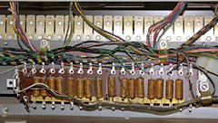
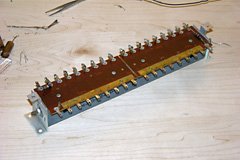
The vibrato delay line consists of capacitors and inductors (not visible) which delay and filter the signal.
Hammond tonewheel organs beginning with the BV and CV models feature a vibrato system which modulates the frequency (and to a lesser extent, the amplitude) of the tones produced by the organ at a rate of about 6.9Hz. Unlike later all-electronic organs which modulated the tone source, the Hammond vibrato system modifies the tones themselves, on their way from the keyboard into the amplifier.
How is this possible? That was the question that Hammond engineers asked themselves in the 1930s and was answered by John Hannert’s invention of the vibrato delay line and scanner. This system works by first feeding the audio signals through the delay line, which is a series of second order passive all-pass filters. Each filter has the effect of slightly delaying the signal (about 50μs per filter stage). The length of the delay depends on where along the delay line you pick up the signal again. The delay line is the electronic equivalent of a tube into which you feed sound from one end, with a series of holes where you can listen to the sounds from. The further down the tube you listen, the more delayed the signal will be.
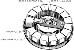
The second part of the Hammond vibrato system is the scanner, which consists of sixteen sets of fixed capacitor plates and one set of plates mounted on a rotor. The moving plates are interleaved between the fixed ones, much like the air-gap capacitors used in older radios. Each of the fixed plates is connected to a point on the delay line. As the rotor turns, the moving plates move past each fixed plate in turn, allowing the signal from that plate to pass into the moving plate (recall that audio signals are AC, and that AC can flow through a capacitor).
The sixteen inputs to the scanner are connected to nine of the outputs of the delay line in such a way that the rotor samples those nine outputs first from least delay to most, then back to least. In other words, if we label those output with the letters A through I, the scanning sequence is [A, B, C, D, E, F, G, H, I, H, G, F, E, D, C, B]. After one scan it starts over from A. Returning to the “long tube” analogy, this is like moving your ear along the tube, starting at the hole right beside the sound source, moving to the far end, and then back again.
In effect, scanning back and forth along the delay line is like moving toward and away from a sound source. This causes a change in frequency due to Doppler shift. Because the filters slightly attenuate the signal, there is also a change in amplitude.
Console Organ Vibrato
In a Hammond console organ (B, C, and A-100 series), there are three different vibrato settings and eighteen stages in the delay line. Using a complex multi-pole switch, the different settings connect to different sets of points along the line. At the V-1 setting, only the first nine stages are used. Twelve stages are used for V-2, skipping a few along the way. The highest setting, V-3, uses all eighteen stages, skipping half of them (more are skipped in the middle than at the ends of the delay line). All three settings have the first two stages in common.
Spinet Organ Vibrato
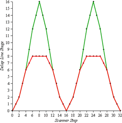
In the M-100 series of spinet organs such as my own M-111, there are only sixteen stages in the delay line and two vibrato settings. The small setting uses stages [0, 1, 2, 4, 6, 7, 8, 8, 8, 8, 8, 7, 6, 4, 2, 1], while the normal setting uses [0, 1, 2, 4, 6, 9, 12, 14, 16, 14, 12, 9, 6, 4, 2, 1]. The effect of these stage sequences is readily visualized by looking at a graph. The graph shows two complete vibrato cycles (corresponding to two revolutions of the scanner) at the normal and small settings. The horizontal axis represents elapsed time (in scanner steps) and the vertical axis is delay (in delay line stages):
The skipping of stages isn’t uniform, but it’s pretty close for the normal setting. However, it’s terrible for the small setting, with stage 8 used for five consecutive scanner steps in a row. This means that during those five steps, there’s no effective motion and thus no frequency shifting. It’s like the vibrato is turned off during a third of each revolution of the scanner. None of the settings on the console organs have such a plateau.
Why did Hammond do this? I don’t know. Can it be improved? Yes!
Improving the Small Vibrato
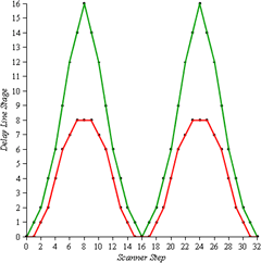
My first inclination was to come up with a small a scanning sequence that makes the (red) graph look as close as possible to a sine curve:
Notice that this one still has flat areas but they are smaller and divided equally between the top and bottom. This sequence would be ideal because it would sound like one were moving toward and away from the sound source in a cyclic manner (like sitting on a merry-go-round, listening to an organ-grinder off to one side). The problem with this sequence is that it has only one point in common with the normal setting, namely the connection to stage 0. This means an 8-pole switch would be needed to switch the remaining 8 delay line connections between normal and small, but the M-100 series has only a 4-pole switch.
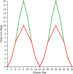
I briefly considered adding some relays to get more switch positions, but since perfect symmetry isn’t required and none of the console organ vibrato settings have plateaus anyway, I came up with an alternate small sequence that can be implemented with the existing 4-pole switch. Its graph, together with the factory normal sequence, looks like this:
Notice that unlike the original small sequence, it goes to stage 10 instead of only stage 8. This places it somewhere between the V-1 and V-2 settings of a console Hammond.
Improving the Normal Vibrato
Can we make any improvements to the normal vibrato scanning sequence as well? I think so. The peak of the factory normal sequence is quite steep, resulting in a rather sudden turn-around from falling pitch to rising pitch. By slightly changing the choice of delay line points near the peak, we can smooth this out a bit, without changing any of the points we’ve so carefully kept in common with the small sequence.
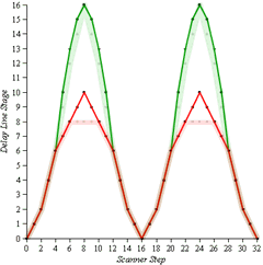
Here then are the proposed new M-100 series vibrato sequences (solid thin lines) overlaid on the original factory ones (translucent wide lines):
Notice that both the normal and small curves are very close to symmetrical, and have the first five points in common. Numerically, the sequences are [0, 1, 2, 4, 6, 7, 8, 9, 10, 9, 8, 7, 6, 4, 2, 1] and [0, 1, 2, 4, 6, 10, 13, 15, 16, 15, 13, 10, 6, 4, 2, 1].
Overhauling the Delay Line
Before attempting to improve the vibrato, it is necessary to restore it to factory specifications if the line box has the older wax capacitors (as shown in the photo at the top of this article). While these were very good capacitors in their time, they don’t hold their specifications well as they age. Their capacitance actually increases over time, which has two detrimental effects in this application:
-
The cut-off frequency of the low-pass filters is reduced, meaning that a larger portion of the sound spectrum entering the delay line will be attenuated. This results in a higher percentage of amplitude modulation, giving more of a tremolo effect.
-
The delay introduced by each stage is increased, resulting in a stronger frequency modulation. To some extent, this makes up for the extra amplitude modulation (i.e. one can still perceive the vibrato within the tremolo).
Overall, these two effects combine to make the modulation too intense. I found that in the normal setting, the frequency would shift so far that it sounded like I was playing the wrong notes. There was also a very noticeable “thumping” due to excessive amplitude modulation.
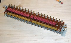
The cure for this is to replace all the capacitors. In my line box, there are fifteen 0.0056μF (5.6nF) capacitors and one 0.0027μF (2.7nF) capacitor, all rated for 200V. I chose to replace these with new polypropylene capacitors of the same values rated for 630V, which I ordered from Digi-Key (part number P3506-ND for the 0.0056μF and P3502-ND for the 0.0027μF).
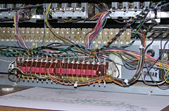
The first step is to remove the delay line from the organ since it is easier to work on it on a workbench. I unsoldered each of the wires connected to the delay line terminals, making note of which wire went where. Then I removed the four screws holding the delay line to the back of the upper manual. Although it’s not necessary, removing the top panel of the organ makes it easier to see what you are doing.
Once on the bench, I used a solder sucker to remove the solder where the capacitors were connected to the common bus at the bottom. I then untwisted each lead from the lower terminal. Next I heated the upper terminal and found that the upper lead would just slide out from under the inductor wires. After all the capacitors were out, I used the solder sucker again, as well as some desoldering braid, to clean excess solder off all the terminals (including the ones that the scanner wires attach to).
I measured the paired 18kΩ termination resistors and got a reading of almost exactly 9kΩ as expected. However, the 1.8kΩ resistor at the input end of the box was reading 2.2kΩ. I didn’t have a replacement 1.8kΩ 1/2W resistor handy, so I wired a 10kΩ in parallel with the existing resistor to bring the resistance back down to 1.8kΩ.
I started by installing the 0.0027μF capacitor on the far left (note that the line box is reversed relative to the schematic – the left end of the line box corresponds to the right side of the schematic). I fed one lead through the lower terminal and held the other lead against the upper terminal with an alligator clip. I then soldered the lower terminal, removed the alligator clip, and soldered the upper lead to the face of the upper terminal. I installed the remaining fifteen 0.0056μF capacitors using the same technique.
Out of curiousity, I decided to measure the capacitance of each of the old wax capacitors. The results were astonishing. Of all the 0.0056μF capacitors, the lowest capacitance I measured was 0.0079μF and the highest was 0.0107μF, a range of 41% to 91% over spec. The average was 0.0095μF, or 69% over spec. The 0.0027μF capacitor measured 0.0045μF.
After completing the recapping, I reinstalled the linebox in the organ and reconnected it exactly the way it came from the factory so I could compare the sound to how it sounded with the old capacitors. The difference was remarkable. There are audio clips at the end of this article if you want to hear for yourself.
Implementing the Improvements
Rewiring the line box for the improved vibrato delay curves is straightforward, so much so that one wonders why Hammond didn’t build it this way in the first place. The following excerpts from the M-100 schematic sum up the modification:

Original factory vibrato scanner to delay line connections. Connections highlighted in red are to be removed.
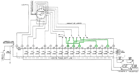
Improved vibrato scanner to delay line connections. Connections highlighted in green are to be added.
Notice that there are connections to non-numbered terminals on the vibrato delay line. Those terminals are already there anyway; they were just not used and not numbered in the schematic. Also note that the stage numbers I’ve been using so far in this article refer to filter stages, not terminal numbers. The easiest way to remember which filter stage is being talked about is to look at the inductor number immediately to the left of the connection in the schematic. For example, the terminal numbered 11 is stage number 9. There is no inductor to the left of terminal 1, so we’ll call that stage 0. To avoid errors, I wrote the stage numbers on the line box before I installed the new capacitors.
These are the steps I followed to carry out the rewiring:
- Moved the wire connected to stage 14 left one position (right on the schematic) to stage 15.
- Moved the wire connected to stage 12 left one position to stage 13.
- Moved the wire connected to stage 9 left one position to stage 10.
-
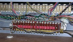
Unscrewed the vibrato switch block from the front panel, slid it out towards the back of the organ and turned it over. I then removed the wire between the three switch terminals that connected three steps of the scanner to stage 8 of the delay line. This left a wire connected to only one switch terminal, which turned out to be the terminal that should remain connected to stage 8.
- Soldered two new wires to the other two switch terminals and connected them to stages 9 and 10 of the delay line (the brown and orange wires in the photo).
- Reinstalled the vibrato switch block.
That’s all there was to it.
How Does It Sound?
In order to be able to make a comparison between the three different stages of this project (before, after recapping, and after rewiring), I made recordings each step of the way. To make it easy to do some signal analysis, each recording consists of only a single note, the A above middle C, with only the 8′ drawbar pulled out. This gives an almost pure 440Hz sine wave.
Each recording below is four to five seconds long. The graphic for each covers exactly four vibrato cycles (four revolutions of the scanner), and was taken directly from the recordings. The changes at each stage are easy to see. The difference between the old and recapped vibrato is also easy to hear, whereas the difference between the overhauled and rewired vibrato is more subtle.
I find the vibrato sounds much better than before. I can now use full vibrato while playing music and it sounds quite nice. Before the overhaul, it was most unpleasant. The recapping made the biggest improvement, but I think that the rewiring has also subtly improved the effect.
Related Articles
If you've found this article useful, you may also be interested in:
- Rebuilding a Hammond AO-29 Amplifier from the Ground Up
- Hammond Organ Tonewheel Generator Capacitor Replacement and Calibration
- Overhauling the AO-29 Amplifier in the Hammond M-100 Series
- Window Seat Bookcase Tone Cabinets for a Hammond Organ
- Retronome – A Versatile Analog Drum Machine for My Hammond Organ
- Adding a Rotary Speaker to a Hammond M-111 Organ

If you've found this article useful, consider leaving a donation in Stefan's memory to help support stefanv.com
Disclaimer: Although every effort has been made to ensure accuracy and reliability, the information on this web page is presented without warranty of any kind, and Stefan Vorkoetter assumes no liability for direct or consequential damages caused by its use. It is up to you, the reader, to determine the suitability of, and assume responsibility for, the use of this information. Links to Amazon.com merchandise are provided in association with Amazon.com. Links to eBay searches are provided in association with the eBay partner network.
Copyright: All materials on this web site, including the text, images, and mark-up, are Copyright © 2025 by Stefan Vorkoetter unless otherwise noted. All rights reserved. Unauthorized duplication prohibited. You may link to this site or pages within it, but you may not link directly to images on this site, and you may not copy any material from this site to another web site or other publication without express written permission. You may make copies for your own personal use.


Bob Sigman
February 06, 2009
I much enjoyed reading your article. I am rebuilding a 1957 B3. I am using a scope on all the output and comparing old values with new values for the TWG. I will now do it for the Vibrato old and new caps. I am glad that the hammond TWG technology isn’t being lost. I have been working on this project about 6 months and loving every minute of it.
Chris Fuller
November 13, 2009
I’m trying to understand this Hammond Model M vibrato and scanner etc, is the motor actually physically turning a wheel in the vibrato scanner? The circular part? What I was trying to figure out how to do was find a way to control the rate of the vibrato with a potentiometer, to dial in on certain frequencies. You said it operates at 6.9 hz, so would changing the voltage from the motor essentially change the hz of the scanner? Once again I don’t really understand this that well, but I think I sort of have a vague idea. Thanks, Chris
Stefan Vorkoetter
November 13, 2009
Chris, the vibrato scanner is indeed physically turning. In the drawing, it is the central part that turns, so that the rotor plates pass through each set of stationary plates in turn (two sets of stationary plates are omitted in the drawing so you can see the rotor plates).
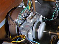
The motor is inside the rectangular box mounted on the right side of the scanner in the photo. This is an AC synchronous motor, and is the same motor that turns the tonewheel generator. Being synchronous, the only way to change its speed is to change the frequency (not the voltage) of the 120VAC that is powering it. And, if you did do this, the organ would be out of tune since the tonewheel generator speed would vary as well.
Michael
December 09, 2009
Great write up!! I saw your link to this at the organ forum and it’s really helpful because I need to change the caps on my A100.
Richard LeClair
September 16, 2010
this is just amazing =@
Delroy White
September 17, 2010
kool
this my type of music
Jurgen Uffink
October 20, 2010
I have got a Hammond M101 that i will give the same treament as you did. that sound so mutch better!
Lennart Temmink
February 21, 2011
Very clearly explained! Maybe the only thing worth mentioning is the way the ‘Vibrato Chorus’ switch adds dry signal to the ‘wet’ Vibrato signal.
Angel Lopez
August 11, 2011
thanks for another great article…
Vagn Mehlsen
September 23, 2011
Thanks for that very informativ article! 🙂
lennart jansson
September 04, 2012
Thank you for an interesting and educational read. But what you learn is that this is sabotage! in my ears sounds original vibrato much better. Richer. Why spend such an effort to get something to sound a lot simpler. Easier to buy a cheap digital organ, then you get that clean simple vibrato. A Hammond is well sound like Hammond and not as a cheap electric organ. – Please note that this is just my opinion! 😉
Stefan Vorkoetter
September 05, 2012
Lennart, keep in mind that the purpose of replacing the capacitors is merely to make the vibrato sound the same way that it did when it was new. After that, rewiring the vibrato is to make it sound more like a Hammond B3. I don’t think either sounds cheap. (I used to have a 1970s Yamaha transistor organ, and the vibrato on _that_ sounded cheap.)
vibrato contrato
September 15, 2012
Hey Stefan! I am really enjoying your article. Doing some work on a M3 vibrato section, you wouldn’t happen to know the output from the vibrato preamp sides? Or from the scanner to the amp?
Robin Easton
September 23, 2012
Great mod and beautiful presentation, writing and use of photos and original drawings is all really great, thanks!.
SANTIAGO
April 13, 2013
Is posible replace a vibrato scanner from a M3 to a Hammond BV?
Regards
Michael
June 28, 2013
Hey Steven what are some replacement caps that can be found since those Panasonics are no longer made?
Patrick B.
September 08, 2013
Great article. Think you could do one for a buss-bar cleaning? There is hardly any information/pictures of this on the web.
TOM
April 22, 2014
I HAVE A HAMMOND T-212-1 ORGAN….THE VIBRATO HAS A PROBLEM.WHEN I TURN IT OFF.ALL THE F KEYS STILL HAVE VIBRATO.DO YOU NO THE PROBLEM HOPE YOU CAN HELP…THANKS TOM
Urs Meyer
September 12, 2014
I enjoyed reading your paper. It adds to the experience I made on adding vibrato scan to the X-77. I actually used a T-Model scanner, had to make the delay line new, with inductors wound on separate ferrite cores. It appears that the tuning of this setup is quite time consuming. If you stumble over a spinet model delay line, let me know. I will buy it. Otherwise I go back to your paper and try to improve that way.
Good job!
Urs Meyer
Alejandro
November 19, 2014
Hi Stefan,
I have a Hammond M111 and volume is low..I replace tubes and nothing happened..Also I open the pedal box and I adjusted on the screw.
Please help me !!
Thanks
Alejandro
Michael
September 02, 2015
Alejandro
I bought a M100 which was almost seized up mechanically.
It’s now working very well but had low volume like yours.
I found that holding Start switch for up to 12 seconds then adding Run switch while holding Start for another 5 seconds made a HUGE difference.
Any shortened sequence made the M100 sound muffled as if the TWG never really got up to speed.
Cheers!
Stefan Vorkoetter
September 02, 2015
I honestly can’t see how that could make a difference. If the tonewheel generator didn’t get up to speed, then the pitch would be way off, but the volume would be unaffected. Is that what you’re hearing? If that is the case, I think you need to do more work on the generator, since something is dragging. Dragging = friction = wear and tear.
John Clark
October 04, 2015
Hi Stefan,
Thanks for taking the time for these great articles. I have a M 102 with AO-29-13 amp. Everything works fine with the vibrato switch off. When I engage the vibrato it works but the sound is very low. Any suggestions on where to start? Thank you in advance for your time herein.
Stefan Vorkoetter
October 06, 2015
Do you have the same problem with both manuals? If not, then it’s probably just a dirty switch contact. If the problem is the same with both manuals, the first thing I’d try is swapping tubes V1 and V2. If the problem now reverses (normal is quiet, vibrato is loud), then you had a bad V1. A bad V3 is another possibility. You could try swapping it with V9. If the vibrato now works, there’s a good chance the percussion won’t (V9 is used in the percussion amp). Those are the easiest things to try without any test equipment. If that doesn’t get you anywhere, some more serious troubleshooting might be in order.
JP Moore
November 05, 2015
I have owned a 1964 Hammond M-101 and Leslie 251 for about 2 years, so I am a novice on original Hammonds. When I play the low C on either manual, it doubles the tone with a lower octave. I cannot find any setting for this on the controls. Is this normal? Can the double-octave be on low C be turned off?
Stefan Vorkoetter
November 05, 2015
That is definitely not normal. Does it happen for all drawbars, or only certain ones?
Danny Shoemaker
November 10, 2015
Stefan,
Nice layout of info, diagrams, and charts. Bravo. When I open up separate tabs for each of the sound samples and listen to them back to back, the full vibrato seems to go through a bit of a rise in pitch, but not so much on the small vibrato examples. Is this just how the website was made, or is that an honest representation of the before and after of each speed? Thanks for all the time you spent putting this website together.
Stefan Vorkoetter
November 11, 2015
Hi Danny. The recordings are actual recordings, so what you hear is exactly what it sounded like before and after. Both full and small do have pitch variation, but by design, it’s much less on the small. Even on the full vibrato, the variation is only about 1/4 of a semitone.
Bernie
November 12, 2015
Stefan, You are incredible!!!! Thank you for you succinct article – I have an Hammond E-100 that with your fine article decided to tackle. I was able to purchase all tubes ($$$$, OUCH) , but never thought about the capacitors.
Your pictures are invaluable ! Also was able to download the Repair manual.
One question please – Your schematic is for a M -100, I have an E -100, are there any differences ?
Thank you in advance for your time,
Respectfully,
Bernie
Stefan Vorkoetter
November 13, 2015
Glad to be of help. Yes, the E-100 is very different than the M-100. They share a few things in common, such as the tonewheel generator, and basic amplifier architecture, but they differ in the details. The E-100 also has a bunch of additional circuitry for things like brush and cymbal sounds, a harp effect, and so on. A complete scan of the service manual is available here: https://ia801009.us.archive.org/26/items/E100ServicePlus/E100%20Service%20plus.pdf
Brian Maes
February 08, 2016
Hi Stefan, I recently saved a Hammond M-111 from being thrown in a dumpster. It took about a month of oiling and starting the organ to get it to make a sound. The loud squeaking and squealing noises have pretty much subsided. Now it plays but very soft. The vibrato doesn’t work either. Do you have any suggestions? Thank you very much. Brian
Stefan Vorkoetter
February 08, 2016
There could be any number of things causing it to play quietly, such as bad tube, corroded tube socket contacts, dirty switch contacts (especially in the Volume Soft switch), dirty drawbar contacts, etc. The vibrato not working could be a bad tube in the vibrato amplifier, or a vibrato scanner that’s not spinning (that’s what was wrong with mine). You can try swapping tubes V1 and V2. If you then get vibrato and the non-vibrato stops working, then you just need a new tube.
John Schulien
December 27, 2016
Hi, Stefan. I just finished carrying out your procedure on my M103. New capacitors and rewired the scanner pattern. It’s back together and working now and seems much improved.
In following your procedure I encountered what I believe to be a missing step. Your modified curve for the regular vibrato changes scanner step 5 from delay stage 9 to stage 10. This is reflected in your schematics but not in your instructions. I believe you need to add a step:
Step 2.5. Move the wire connected to stage 9 one position left to stage 10.
Otherwise your writeup was pretty easy to figure out. Thanks for taking the time to write up this great page and share your mod!
Best regards, John
Stefan Vorkoetter
December 27, 2016
Thanks for catching that! I’ve updated the article (the steps after step 2 have all incremented by one). I’m glad to hear that this writeup has been of use.
John Schulien
December 27, 2016
One particular problem that can occur with Hammond vibrato is motorboating — where the vibrato pulses. I ran into this problem on my M103. It actually was the problem that led me to to this page and led me to recap my vibrato, but the recap didn’t fix the problem.
This video did: https://www.youtube.com/watch?v=LRoK3eNc5pk
It appears that metal “whiskers” can grow inside the vibrato scanner over time, and that when they do, they internally short the plates to ground, which causes unevenness or even dropouts in the volume envelope. I believe that Stefan was encountering this problem when he wrote about periods of almost zero amplitude and his large and small sub-cycles.
After I zapped the scanner (using two 9-volt batteries in series), I got a regular vibrato volume envelope that is a near-perfect sine wave — even better than Stefan’s rewired full vibrato.
Stefan — if you haven’t done this you might want to give it a try. It might just make a big difference!
– John
Stefan Vorkoetter
December 27, 2016
When I first got the organ, the vibrato scanner wasn’t working at all. Its bearing was seized, and the clutch that drives it from the motor was slipping. I therefore completely disassembled and cleaned the vibrato scanner (as described here), so I definitely wasn’t experiencing motorboating.
John Schulien
December 27, 2016
Thanks for the link … I was considering dismantling the scanner but it’s working so well I’m going to leave it alone.
Fredy Schorfhaar
January 16, 2017
Hello Stefan,
i am from Holland and I have a problem with my M111 Spinet Hammond Organ.
I can nowone find in Holland who can help me.
The problem is that the Organ only works with Vibrato on. Whwn I cancel the Vibrato there is tone at all, and also the lower en upper keyboard.
Maybe you no what the problem is ?
Thanks
Stefan Vorkoetter
January 17, 2017
Hi Fredy: It is very likely that tube V2 is bad. Try exchanging V1 and V2. If this makes the organ work only with the vibrato off, then you just need to buy a new tube.
Fredy Schorfhaar
January 18, 2017
Hi Stefan,
Thanks for the response,I have try to exchange the V1 and the V2 the problem is the same. Only the volume is less. The V2 is the 6AU6 and the V1 CV2524, is that normal ? I think thats not the problem because he was working fine.
I have also try to change V3 –> V9 thats also the same problem.
The vibrato is working but I can not Cancel him when I do that there is no Sound !!! Upper and Lower keyboard.
Strange Case is’nt it ???
I didn’t expect that you give an reaction, Thank you very much !!!
Regarts Fredy
Stefan Vorkoetter
January 18, 2017
That sounds like it is very likely either a damaged switch, or a broken wire between the switch and the non-vibrato input of the amplifier. There are many wires connected to the back of the amplifier, but two of them are shielded (metal covering), and go into a small metal box in the middle of the back of the amplifier. If you remove the two screws holding this box to the back of the amplifier, you can check if both wires are still connected. The terminal labelled “A” is for the non-vibrato input, and the other, “B”, is for the vibrato input.
Fredy Schorfhaar
January 20, 2017
Hello Stefan,
I have now put my Finger on the B contact and than there is a big Noise but whwn I put the Finger on the A Contact there is NO noise (oké a very small one). So I think maybe there is something wrong whith the Amplifier ????
Regards Fredy
Stefan Vorkoetter
January 21, 2017
Yes, it sounds like there is something wrong with the first stage of the manual amplifier, which is V2 and its associated components. The fact that vibrato works, means that V1 and everything else is working.
Fredy Schorfhaar
January 23, 2017
Hello Stefan (again),
Is it possible to change the Cable from V2 and V1 than he must work without Vibrato ??? Than I use also an Leslie and i really don’t use the vibrato !!
Thanks Fredy
Stefan Vorkoetter
January 30, 2017
Yes, that should work. You might want to relabel your Vibrato switches, since they will now operate opposite of what they say on them.
Fredy Schorfhaar
January 31, 2017
Oke thanks you very much for the Help !!
Regarts Fredy
Jan Hansen
April 08, 2017
Thanx for some very educational articles about Hammond Organs.
I have been wanting to get hold of a Hammond console organ for a couple years now , actually just any console transistor or tonewheel would do .. consoles are very hard to get by in scandinavia, no matter what brand, sadly.
But I love how simple these old organs electronics is to understand, that just a basic electronic knowledge makes you able to understand how things work.
Its just too bad that I can find quite many fairly cheap refurbished A-100 series organs in the states, but the shipment to Europe would cost twice what the I’d have to pay for the Organ.
I am tho not convinced that the reviring actually does any good to the simple one note sound in your example sound files. To my ear it would be perfect with just the recaps. The curves “looks” prettier rewired, but creates a little too much pulsating especially on the full vibrato. The vibrato effects often sounds more realistic or “pleseant” on eg most sampled instrument sounds by using a triangle curve rather than a sinus curve, or something in between the two. But in general vibrato should be added in moderations imo, since it will always just be a one or two-dimensional effect at best, wich is why the Leslie effect is so hard to emulate, because its almost impossible to cheat the ear to think its hearing all 4 dimensions of the effect from just 2 stationary speaker points
Ian O'Brien
October 14, 2017
Hey thanks for article! I finished your mod and cap replacement the other day and I dismantaled the scanner and gave it a good cleaning before then. The whole reason for all the scanner work was because I was getting what sounds like a ground loop (heart beat thumping)when I have the “vibrato small” tab down. My scanner sound fabulous now but sadly I still have the ground loop 🙁 I’ve also noticed that the braided ground wire that goes from the scanner to the amp is picking up noise. So would that mean that my ground problem is inside my amp? I have a m-102. Thanks for any help!
Stefan Vorkoetter
November 02, 2017
It sounds like your ground wire isn’t properly grounded. Make sure that it is screwed down tight where it goes through the cover into the amp, and also ensure that the cover itself is screwed down tight to the amp.
Alek Zamonski
March 22, 2019
Thank you very much for this detailed description of your process as well as all of your other overhauling videos. There’s is certainly a good difference before and after the recap (better obviously being after the recap). While reading your procedure the wiring improvements certainly seemed to make a lot of sense, but after listening to the recording I think I may like Hammond’s original Vibrato from the factory better. It seems that your rewiring job is adding a new tone in and completely changes the Vibrato. It quite heavily alters the tone and almost sounds out of phase. That being said, it is all a matter of preference and there’s certainly something to gain from that improvement if you like the sound of the rewired Vibrato. I’ll probably just stick to recapping though. Thank you very much again though for this detailed description of your mod and recap!
R
April 17, 2019
Hi Stefan,
Surfing today, if I ever get down and do one of your projects, I will more than happy to buy you coffee and A DOUGHnut.
But Today I just want to recognize you. You really did some great research and reported your finding very professionally.
great job
Yulik
November 19, 2019
Dear Stefan,
Thanks for your helpful article. We got a B3 in the studio which had the same problem and I’ve rebuilt the delay box the same way you did. It seemed to sound better but honestly I’d appreciate some external judgement.
Would be nice of you if you listen and give your opinion.
Thank you very much.
https://photos.google.com/share/AF1QipNXeg8cx176mhbfBmzIwVB60HgLKWDvqJ88h5R_a0So43I3IYCNelSeRRdsGg-pjg?key=OEpOX3RHT3lNcVhad2dpUlJpTmp3QzJWbm8yMVZR
Stefan Vorkoetter
November 20, 2019
I’m probably not the best judge, but perhaps others will chime in. It’s also a little hard to tell from just listening to a pure tone.
RV
February 24, 2021
Hi Stefan, I’m about to recap my VLB for my ‘62 B3. I was prepared to solder the top lead of the cap by splice to the old clipped cap wire, as I don’t want to risk messing with the coil wires. However, you stated that when you heated the top connection that the old cap lead simply slid out from under the coil wiring. I can see that the coil wires appear to be wrapped, so it may make sense that they would “spring” when the solder melts. Can you provide a bit more detail? Did all of the coil wires stay put? None fell off or loosened? Anything else? I need a lot of reassurance before I attempt that versus clipping and splicing. Thanks!
Greg B
September 09, 2021
Hi Stefan,
Thank you for sharing your knowledge and techniques on the Hammonds. I have a B-3 with a Vibrato that does not vibrato. With vibrato off everything appears to run fine. With the Vibrato on I get a slight change in sound when rotating the Vibrato Chorus knob but no vibrato. I’ve tried swapping tubes V1 and V2 and the same symptoms. I rigged up three 9 volt batteries for 27 volts and zapped the lugs on the vibrato scanner, this did not change the symptoms either. Is there anything else to check or am I looking at disassembling and cleaning the scanner?
Thank you Greg B in Maryland USA
Stefan Vorkoetter
September 09, 2021
Hi Greg. From what you’ve described, it really does sound like the problem is that vibrato is failing to rotate. Mine was like that when I first got it. I ended up having to disassemble it, as (what I recall) it was stuck rotating on its bearings.
Tom M
December 05, 2021
Hi Stefan-
I’ve cleaned and “rebuilt” (rebuilt seems like an overstatement for disassembling and cleaning…) multiple Hammond vibrato scanners as they are frequently stuck as you found on yours. I also replace the threads by default (run motor, too) as it is relatively easy to do and saves grief later. Interestingly, I’ve never seen whiskers inside any scanner, ever. They are all over every other metal part, but not the scanner.
I just did one from an M3 this weekend and when setting the rotor height within the plates to center the air gap I found that when rotated around there was quite a bit of variance in the air gap due to a general tilt. This particular scanner did not have any shims for the inside can when I took it apart, but I have some shims from a few spares so I added a few to get it more level. It still wasn’t great, but I set the rotor height carefully so that it would track in any orientation at max play without hitting any plates. All back inside the organ and it works and sounds fine.
But I was thinking that I probably should have measured the capacitance of each set of plates with the rotor fully aligned to see if there is a lot of variation due the the changes in air gap as the rotor spins.
Do you think the air gap actually matters or as long as there is no contact the capacitance will be relatively the same?
George Lemaster
January 10, 2024
Delay line wax and plastic covered paper caps increasing value out of tolerance, I attributed to absorption of moisture by the paper dielectric, as the seal is imperfect. In Baldwin organs the plastic case caps would swell and crack open.
George Lemaster
January 10, 2024
Working for a large Hammond dealer in 1970’s I rebuilt many scanners, we would keep one or two rebuilt types in the truck. A common complaint was shorted a scanner about 1-2 weeks after someone oiled the organ. Especially if the felt pad over the motor was dry, excess oil flowed through the copper pipe with oiling thread and dumped oil into the scanner. After time the oil saturated the bottom bakelite insulators would short, some reading nearly zero ohms. I rebuilt scanners removing oil, installing new insulators from Hammond (from large bags). Also removed the copper pipe, leaving the oiling thread only so excess oil would not go into the scanner.
Unsure why oil seemed to cause the insulators to short, maybe causing dendrite growth?
Mic Hess
February 11, 2024
I really appreciate the effort you put into this article. It is very helpful. I have maybe a slightly different issue that somebody may have seen this before.
I bought a 1963 B3 that was used a lot by a professional keyboardist. It also sat in an unheated storage unit in Idaho. When I turn it on, once the amp warms up it starts a thumping sound, with about the same frequency as the vibrato. With the vibrato off, it is quite noticeable, and doesn’t quit no matter how long I leave it on. If I turn the vibrato on, the thumping is very loud.
I haven’t seen this addressed anywhere and would appreciate any guidance.
M. S.
September 30, 2024
Sorry, but I don’t agree that the modified vibrato sounds better. The ingenuity that went into designing Hammonds has largely been forgotten by time.
The original ‘normal’ vibrato gates the delay line with a triangle wave. This is perceptually more distinct than a sine wave gate, which sounds smoother but more dull. Just listen to a ‘raw’ sine vs. triangle wave and you’ll see what I mean. You may argue you’d prefer the latter, but I think this was a deliberate design choice by Hammond engineers to really have the vibrato sound ‘stand out.’ As for the ‘small’ vibrato, I think the idea there was to have a contrasting sound, hence the flat peaks. Your modification just reduces the amount of vibrato, while leaving the ‘sine-like’ character essentially the same.