Stefan’s Volksplane Construction Log
Fuselage Assembly
November 19, 2011
Continued from Fuselage Construction: Sides.
2011-Oct-11: Although I didn’t realize it at the time, the previous entry would record my last time working on the Volksplane for over four years. A home renovation meant I wouldn’t be able to work on it for six months, but things took longer than expected, other projects drew my interest, and the VP-1 just sat there until today, four years and two months later. Some words of encouragement from the members of the Volksplane forum, and the local RAA chapter, was what it took to finally get me going again.
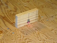
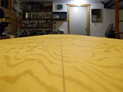
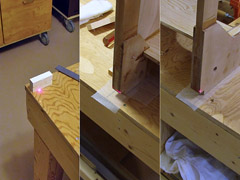
I decided to start with something easy, so I spent half an hour drawing a perfectly straight line down the centre of my workbench. To do this, I used a laser, a wooden target block with a vertical reference line and a notch at the base, and an extra fine Sharpie permanent marker.
I marked the centre of each end of the bench, placed the laser at one end and the block at the other, and adjusted the laser until the reference line was centered in the red dot. I moved the block along the bench, making a mark every foot or so. A notch in the bottom of the block ensured that the pen would be exactly aligned with the reference line. I then used the Sharpie and a steel straightedge to connect the marks.
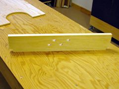
2011-Oct-12: Today I started making F-9, the seat support. I was a bit unsure as to the material to use, since the plans just said “P”, which could mean either pine or poplar. Evans usually uses the notation “W.P” when pine is called for (white pine), but I took a quick look at the VP-2 plans, where this same part, which has to hold twice the weight there, was clearly labelled as “White Pine”.
I started with a nice straight and flat 24″ length of clear pine 1×6 (which is actually 3/4″ x 5-1/2″) and ripped it down to 4″ width on my bandsaw. I then marked one end with a small machinist’s square and crosscut that, also using the bandsaw (the ends of lumber are rarely exactly square to the sides). With two parallel sides and one square end, I then measured, marked, and cut the other end. As a double-check, I held this up to the fuselage bulkheads to ensure it was exactly the right length (22″).
2011-Oct-13: I only got as far as cutting F-9 to its overall size yesterday, so I finished it today. I marked the locations of all the control cable clearance holes as per the plans, and drilled them with a 3/4″ Forstner bit on the drill press. To notch the corners, I used the same technique that I’d used on the bulkheads. Using scraps of longeron stock, I checked that the notches were exactly the right size.
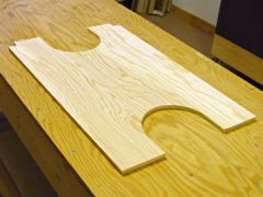
The next step was to make the seat itself. I had originally planned on making this from two laminations of 1/4″ marine plywood, then decided to use a single piece of 1/2″ birch plywood, and finally settled on ordinary fir plywood instead. Although this piece has to hold me up, it is well supported by F-3, F-9, and F-4, and is not a structural member of the airplane. We have a very good wood store in the area, Snider Plywood Specialties, which carries very good quality plywood and will cut and sell you any fraction of a full sheet that you might need. I found a nice piece of G1S 1/2″ 5-ply fir that was actually equally good on both sides, and chose this to make the seat from.
I cut it slightly over its final overall size using a circular saw and home made fence, and finished the edges on the router table. The two large cut-outs were marked using straightedge and compass (see, geometry class was not pointless), and cut out using a jigsaw fitted with a fine-toothed laminate cutting blade. I cut the 1″ square corner notches using the same technique described above for the 3/4″ notches in F-9.
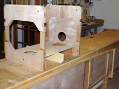
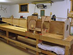
With the seat and support completed, I decided to set up the main bulkheads and seat assembly to see how they all fit together. It’s starting to look like an airplane (if you squint a little, or maybe a lot).
2011-Oct-19: Before assembling the fuselage, the locations of the firewall, forward bulkhead, seat support, and aft bulkhead must be clearly marked on the workbench. I had to do a bit of arithmetic to figure out exactly where each part goes, and came up with the following (measured from the front of the firewall):
| Front of Firewall: | 0″ |
| Front of F-3 lower web: | 29-7/8″ |
| Front of F-9: | 43-1/8″ |
| Back of F-4 sheeting: | 57″ |
| Back of sternpost: | 176-1/2″ |
I made all the measurements using a tape measure, but when I went to double check them with a precision steel rule, found that I was off by about 1/8″ by the time I got to F-4. Holding the rule against the tape measure, I discovered that the markings on the tape were further apart than those on the rule (to the tune of about 1/16″ over 2 feet). I started comparing all my various measuring tools, and found that only this one tape measure had this discrepancy. The next day I bought a new right-handed inches-only tape measure from Lee Valley Tools. Did you know that most tape measures actually work better for left-handers?
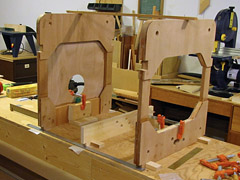
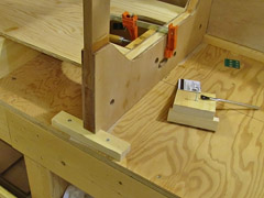
2011-Oct-26: To accurately position F-3 and F-4, I nailed some small pine blocks to the bench, lined up with the lines I had drawn the previous week. I then made some clamping blocks from scraps of 3/4″ plywood and 2×4 lumber. Each bulkhead was held up against the pine blocks, and the clamping block was nailed to the bench against the other side. I could then line up the centre mark with the bench centre line, and clamp the bulkhead to the bench.
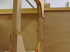
I used a carpenter’s square to ensure that the bulkheads were vertical, and tack nailed a strip of wood across the tops to help keep them that way.
The front of the seat is supported by wooden blocks glued to the back of F-3. These blocks are 4-1/2″ wide and 4″ high, and I cut them, from 3/4″ clear pine, so that the grain would run vertically (although it probably doesn’t matter).
Using a sanding block, I slightly relieved the lower front and back edges of the seat, since there is a slight glue fillet where the rear web of F-4 meets the lower cross member, and there would be a fillet where each forward seat support block is glued to the rear web of F-3.
2011-Oct-29: I checked the alignment of F-3, F-9, and F-4 with a metal straightedge and discovered that F-9 was about 1/32″ too long; when it was aligned on one side, it protruded slightly on the other side. I used the router table with a jointer fence to shave a bit off of the end, and then used the bandsaw to bring the corner notch back to the right size.
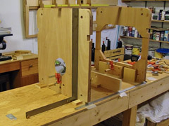
Forward seat blocks glued to F-3. I checked the alignment of all parts with a straightedge and carpenter’s square.
The next step was to test fit the seat. If all was well, it should fit exactly into the space between the front lower webs of F-4, and also fit exactly against F-3. What I found though was that it was not centered on F-3. I carefully double checked everything, and determined that the seat was perfectly square, but that my workbench centre line had a slight wobble at F-3. I decided to simply shift F-3 over for now and worry about overall alignment later.
Once the seat was centered, I used it to position the forward seat supports and then marked their outlines on F-3. I had planned to glue the supports to F-3 with the bulkhead clamped to the bench, but found that it was too difficult to apply uniform clamping pressure. After applying glue to the blocks and tacking them in place so they would not shift, I flipped F-3 upside-down, which made it much easier to clamp the blocks. This was the first time I’d glued anything on this project since I’d set it aside four years ago.
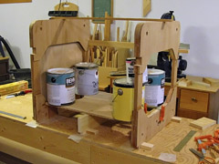
2011-Oct-30: I flipped F-3 back the right way up, and using a chisel, carefully removed the excess glue along the top of the seat support blocks. I inserted the seat to align F-3 again, and checked one last time that F-3, F-9, and F-4 were vertical. I then mixed up a batch of epoxy, and applied it to all the mating surfaces (front and back edges of the seat, seat corner notches, top of the forward seat support blocks and F-9, and the top of F-4’s lower cross member). I lowered the seat in place, and then weighed it down with cans of paint.
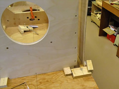
2011-Oct-31: After the seat had dried, I loosened the clamps holding F-3 and F-4 to the bench (and removed the blocks holding F-9), and carefully tapped the whole assembly back into alignment. To double-check this, I made marks at each end of the bench, 11″ from the centre line. At one end I placed a laser, and at the other a target. With the beam hitting the target’s centre, it could be seen grazing the sides of F-3, F-4, and F-9.
2011-Nov-02: Four years ago, I put off drilling the firewall engine mount bolt holes and cutting the lightening/magneto hole to leave my engine options open. Since then, I’ve decided I’m definitely going to use a VW engine, mounted as Evans intended. So I went ahead and cut and drilled the holes, since this would be easier to do while the firewall was still a separate piece.
The mounting holes are too far from the edge for me to drill them with my drill press, so I drilled them freehand, with a cordless drill and 3/8″ brad point bit (this is easier to start on an exact spot, and leaves a clean entry and exit). I was careful to keep the drill perpendicular to the surface. I cut the 8″ diameter hole using a handheld jigsaw and fairly fine-toothed blade that cuts on both the up and down strokes (to leave a clean edge).
Finally, I fastened the firewall to the bench, using the same technique as for F-3 and F-4, with the exception that instead of a clamp, I used a #8 wood screw through a pre-drilled countersunk hole to fasten it to the clamping block. This avoids any possibility of it shifting.
2011-Nov-03: Today would be momentous. The fuselage sides had been sitting on my workbench, and later in a rack on the side of my workbench (visible in an earlier photo on this page) since 2007. Today they would come out of storage, and the rack would come down.
The first thing I did was to test fit the left hand side to the bulkheads. Since I had used the bulkheads to position the longerons during construction of the fuselage sides, I had no concerns that they wouldn’t mate up. However, I did discover that I had neglected to remove the glue squeeze-out from the longeron-to-skin joint where seat support F-9 would join, and this prevented the side from being pushed all the way into the notches. Test fitting proved its worth!
While I had the fuselage side in place, I nailed a block to the workbench against the front of the lower longeron, and then nailed another block on top of that at a slight angle. This would make it easy to guide the fuselage side back into exactly the same position later when gluing it in place.
With everything aligned and properly fitted, it was time to glue the fuselage side to the bulkheads. I laid the side on the floor, face down, and brushed epoxy where the bulkheads would meet it (I’d outlined these areas during the test fitting). I also applied epoxy into the bulkhead notches to make sure that everything would get thoroughly glued.
Next, I lifted the fuselage side into place, first pushing it forward against the guide block by the firewall, and then easing it into the bulkhead notches. Once it was most of the way in, I double checked the position of the support I’d placed at the aft end, and then went back and pushed the side the rest of the way into the notches.
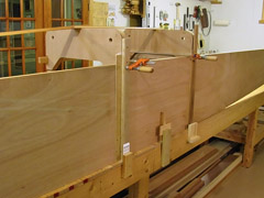
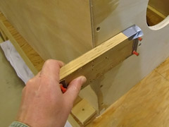
To clamp the side in place, I used very slightly bowed pieces of 1×2 lumber. These were held against the lower edge of the fuselage by blocks screwed to the side of the workbench, and against the upper edge by 2′ long clamps. The other end of each clamp was against a scrap piece of stock resting in the upper bulkhead notches on the other side.
The fuselage was clamped to F-9 in a manner similar to the lower clamps at F-3 and F-4, except I used just a 4″ long piece of lumber, and the clamping block was rigged to apply pressure to it about half way up F-9.
To make sure that the bulkheads wouldn’t shift from the clamping pressure at the bottom, I had screwed pieces of 1×2 pine blocks to the bench in the bulkheads’ lower notches.
With all the clamps tightened (but not too tight), the slightly bowed 1×2 pieces straightened out and applied even pressure to the fuselage skins against the bulkheads. After a few minutes, I inspected each joint from the inside of the fuselage, and observed fairly uniform amounts of squeeze-out from all the joints.
Using an old credit card cut at an angle of slightly sharper than 90° and with the corner bevelled slightly (much smaller than the normal curved corner of a credit card), I removed the excess glue, leaving just a slight fillet. Using another card cut without a bevelled corner, I removed more glue from the locations where quarter-round will later be installed. (It seems that credit cards are very useful when building an airplane.)
By the way, I always return all the squeezed-out glue that I remove back to the mixing container. By comparing this to how full the container was initially, I get a good idea of how much glue was left in the joint. If I get more than half of it back, I’ve probably applied too much clamping pressure. If I don’t get any back, then I didn’t use enough glue and/or pressure.
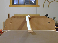
2011-Nov-04: Installing the right hand side of the fuselage took a lot less time than the left, probably because it’s always easier the second time you do something. As before, I first test fitted the side and adjusted the blocking under the tail end to ensure that the top edges of both sides were at the same height along their whole length. Placing a straight board across the back of the fuselage made it easy to confirm that it was level relative to the tops of the bulkheads.
Once again, I nailed a stop block and guide block to the bench at the front so that it would be easy to get the fuselage side back into position after applying the glue. I also screwed blocks of 3/4″ square pine to the bench on the opposite (left) side to keep the fuselage from shifting sideways from the clamping pressure that would be applied on the lower right side.
After that, the process of installing the right side was virtually identical to installing the left side. Once everything was clamped and the glue squeeze-out scraped off, I double checked the alignment one more time before calling it a night. I came back the next morning, relieved to find that nothing had moved.
2011-Nov-08: With the T-88 cured, I removed the clamps and blocks holding the right fuselage side to the bulkheads. I then screwed pine blocks to the bench at each bulkhead, just like I’d done previously on the left side. These blocks were to ensure that the fuselage could not rotate while I bowed the forward fuselage sides inward to reach the firewall.
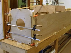
After inserting wax paper under the firewall’s lower corners, I applied glue to its edges (including the fir corner reinforcement cleats). I made sure to apply plenty of glue into the notches too, and then used clamps to draw the sides inward to the firewall. Using four clamps, against 18″ long pieces of 1×2 lumber, ensured even clamping pressure across the mating surfaces. I was pleased to find that the 5° bevel cut into the firewall edges mated perfectly with the curved-in fuselage sides.
Once everything was clamped in place, I checked the alignment once more, and then proceeded to remove the excess glue, being careful not to get any into the bolt holes near the edges of the firewall.
2011-Nov-10: I decided to let this assembly cure for a full 48 hours before removing the clamps. In addition to fully curing the T-88, it also gave the fuselage sides time to adapt to their new bowed shape.
The sides were intentionally left a little long at each end, so I was now faced with the job of trimming off the excess. I decided to use a flush-cutting saw that I’d purchased from Lee Valley Tools. This saw is intended for trimming off wooden plugs without marring the surface, and it seemed ideal for this job as well.
It did work, sort of, but since this saw intentionally has its teeth set in one direction only, it tended to wander away from the firewall. It also tended to splinter the outer surface of the plywood, although just a little bit. I only had time to trim the right hand side today.
2011-Nov-12: Today I used the flush cutting saw to trim the left hand fuselage side overhang. Once again it tended to wander, but I was careful to only cut on the inward stroke to avoid splintering. Once I was done with the saw, I used a small hand plane to get rid of most of the rest of the overhanging material. I trimmed the lower longerons by shaving off a bit at a time with a very sharp chisel, since the plane blade could not cut close enough to the bench.
Finally, a sanding block, with one ended duct-taped over to prevent marring the firewall itself, brought the plywood sides and spruce longerons flush with the front of the firewall.
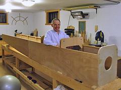
By this time, a lot of tools and wood scraps had accumulated around the workshop, especially on the workbench inside the fuselage. I decided to spend some time cleaning up, since clutter tends to slow me down.
2011-Nov-19: I didn’t have any time to work on the plane during the last week, but this evening I had a few minutes to spare. I’d been studying the plans for the cockpit floor, and wondering if I’d be able to reach the rudder pedals in their designed location.
To find out, I climbed in (for the first time ever), found a comfortable seating position, slightly bent my knees, and then asked my wife to mark the workbench at the bottom of my heels. I was surprised to discover that I needed the faces of the pedals to be a full 14″ aft of the firewall. This moves the location of the front of the pedal mounting block to 12-3/4″ aft of the firewall instead of the 8″ shown on the plans. To accomodate this location, I may need to move the elevator cable turn-around pulley slightly further aft than designed as well.
Disclaimer: Although every effort has been made to ensure accuracy and reliability, the information on this web page is presented without warranty of any kind, and Stefan Vorkoetter assumes no liability for direct or consequential damages caused by its use. It is up to you, the reader, to determine the suitability of, and assume responsibility for, the use of this information. Links to Amazon.com merchandise are provided in association with Amazon.com. Links to eBay searches are provided in association with the eBay partner network.
Copyright: All materials on this web site, including the text, images, and mark-up, are Copyright © 2025 by Stefan Vorkoetter unless otherwise noted. All rights reserved. Unauthorized duplication prohibited. You may link to this site or pages within it, but you may not link directly to images on this site, and you may not copy any material from this site to another web site or other publication without express written permission. You may make copies for your own personal use.


Mike Walling
November 04, 2011
Great site Stefan & very interesting – waiting to see what colour scheme you’re going to use
Stefan Vorkoetter
November 04, 2011
Hi Mike. Thanks for the comments. I’m waiting to see what colour scheme I’m going to use too. 🙂 I’m sort of torn between something completely retro (bare wood and natural linen), or something modern (with an EFIS in the panel). It’ll be nice to get to the point where I have to make that decision.
Darren Barnfield
November 04, 2011
Stefan, Great to see you found the motivation. Well done mate. All you have to do is complete one thing at a time and before you know it you will have it done.
Ed Dougherty
November 05, 2011
This could win the Pulitzer Prize in construction logs! Fantastic.
Morgan Wadsworth
November 05, 2011
Great to see you are back at the build. My set of plans are still collecting dust and it’s getting harder and harder to figure out when I could start my build. For now I’m going to live vicariously through your build. By the way, I bought the plans in part because of your build log that you started many years ago…so it’s really great to see you back in action. Cheers
Robert Edward Scrivener
November 11, 2011
Very impressed with your meticulous write ups! Please keep on building and blogging it!
Gustavo Muller
December 18, 2011
Great work ! keep working
Ricardo Volksplane
February 05, 2012
I bought the plans was 2010. When i saw you log i did my first move. Now we (my brother in law and i) have two rudders almost done… Thanks for inspire us 🙂
Ron Dunn
March 07, 2012
Hi,
good work. I took 5 years to REFURBISH by old VP1 and had to wear a few small mods that have made the plane a little heavier.
The original builder enlarged the flont screen and put in a steel tube rollover cage and also added a steel rollover cage at the rear of the seat.
the aircraft has a conopy and the wheels/brakes are from an Auster aircraft – very heavy!
Miguel Cortes
April 26, 2012
i like your comments on your project hope mine will comr out good when i start working on it im studying plans yet
Jean-Paul Roy
August 15, 2012
Hi Stephan. Your work and log is very inspiring me. I’m looking for something to build and haven’t come with a choice yet. Am I missing something but you haven’t talked wings yet.
Congratulation for such a good job.
Jean-Paul
Thomas Poellmann
November 30, 2012
Hi Stefan,
what happens in the meantime? Did you finish the fuselage already? When can we see the next pictures?
I am building a VP-1 too, and I am almost in the same state. Elevator, rudder and fuselage are finished. It took me the last half year to build the landing gear.
Greeting from Germany
g.ahmed
February 05, 2013
hi/thanks the trouble you took to right down with every detail of the vp1.it real helped me to understand the plane.
best regard G.ahmed
Jeff
March 06, 2013
Great work on the airplane and your build log. I followed this years ago found it so motivating. I checked it tonight on a whim and was so glad to see you picked it up again! Please keep going!
salvador
March 30, 2014
Iam building a vp-1 it is over 80% the last a finished was the fuel tank , it was make like the plans ,but with mold ,Idont like how MrEvans fixed the wind scren so I have changed it ,now the bolt are not inside the fuel tank ,and to keep out the wind I have maked it.is not easy to explain but I think it will work good.
David Ray
December 16, 2015
Just wondering if you ever completed your VP1 and have it flying?
I certainly hope so… after all the hard work you have put into it.
Cheers
David
Stefan Vorkoetter
December 16, 2015
No, unfortunately it’s not done yet, and hasn’t been worked on in quite a while.
Renato
October 20, 2017
Hello, Stefan!
Will you complete the construction of the Volksplane?
If one day you have an interest in selling the parts, remember me.
I live in Brazil and here unfortunately it is difficult to find material to build the volksplane.
Thanks for your website information!
Regards!
PAULO CENTRES
June 05, 2018
Hi, my name is Paulo. I have a volksplane that was built by my father. I have some doubt and I wonder if you can help me. If you have time, I will write you asking you some things.
best regards
Paulo.
Stefan Vorkoetter
June 05, 2018
Hi Paulo. I’m far from being an expert. I suggest you join the Volksplane discussion group at https://groups.yahoo.com/neo/groups/volksplane where a lot more experienced folks can help you.