Measuring Up
September 1, 2004 for QuietFlyer Magazine
To measure is to know. In electric flight, there are a great many variables that affect power system performance. Fortunately, many of these can be measured, and the resulting knowledge used to make improvements. In this article, we’ll look at how to make these measurements and put them to use.
The Multimeter
One of the most useful measurement tools to the electric modeler is the now ubiquitous digital multimeter. These are available in many places (auto parts stores, hardware stores, Radio Shack, etc.) and covering a wide range of prices from $15 to $1500 or even more. However, a super-accurate top-of-the-line meter is not needed. Any decent meter with 3 1/2 or more digits of precision and milli-Volt (mV) resolution will do. The ability to measure high currents is handy, but as we’ll see later, not necessary.
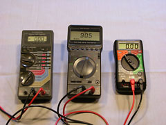
A collection of digital multimeters. The one on left is about 15 years old, while the one on the right is brand new, does all the same things, at a quarter of the cost.
A quick note on precision: If a meter could display numbers from 000 to 999, it would be said to have 3 digits of precision, whereas 0000 to 9999 would require 4 digits. Most meters can display numbers from 000 to 1999 or from 000 to 2999. These meters are said to have 3 1/2 digits of precision, because they can display some 4 digit numbers, but not all of them.
One other feature that many digital multimeters have is auto-ranging. Instead of you selecting the appropriate range of, for example, voltage to measure, you only have to specify that you are measuring voltage (as opposed to current, resistance, etc.). The meter will figure out what range to use automatically. Personally, I prefer to turn this feature off, or use a non-auto-ranging meter, because auto-ranging can take a while, by which time the measurement may have changed.
Let’s look at some of the things that can be measured in a power system, and then how to make use of this information.
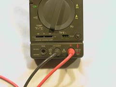
For measuring voltages, the black meter lead is connected to the terminal marked "-COM", and the red lead to the "+" terminal.
Voltage
There are a number of places in an electric power system where it is instructive to measure voltage. The three most useful are: at the battery, at the input to the speed control, and at the (brushed-)motor terminals.
To measure a voltage, first set the multimeter to an appropriate DC Volt range (the ranges are labeled on the dial with the maximum voltage they are intended to measure). Select the lowest range that is higher than the expected voltage. For example, if you are measuring voltages in a 10-cell NiCd or NiMH power system, the highest voltage you are ever likely to encounter is about 16 Volts (when the battery is fresh off the charger). If your meter has 3V, 30V, and 300V ranges, select 30V. If you select too low a range, the meter will just blink or beep when attempting to measure a higher voltage. At too high a range, the meter will work, but will not provide as much resolution (for example, on the 300V range, it might indicate to only the nearest Volt, instead of to the nearest tenth of a Volt on the 30V range).
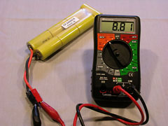
This partially charged 7-cell NiCd battery reads 8.81V, which corresponds to 1.26V per cell. Under load, this voltage would be lower, perhaps 7.7V.
Connect the test leads to the meter. Most meters have three sockets for test leads. Connect the black lead to the one labeled "COM" or "-". Connect the red lead to the one labeled with one or more voltages, or "+". Make sure the red lead is not connected to the terminal labeled "UNFUSED"; this terminal is only for measuring high currents, not for voltage measurements.
Finally, connect the test probes or clips to the location being tested. For example, connect red to the positive motor terminal and black to the negative terminal. Depending on what you are measuring, test leads with either probes or alligator clips might be more appropriate. By the way, one nice thing about a digital multimeter is that it will work even if you connect the leads backwards; you will simply get a negative reading.
Current
Current measurements are done differently than voltage measurements. Instead of connecting the meter across the component being tested (motor, battery, speed control), the meter is connected in-line with the circuit being tested. Furthermore, most digital multimeters provide two different ways of connecting the leads to measure current.
For low currents, typically up to 300mA (i.e. 0.3A), the leads are connected to the meter in the same way they are for voltage measurements, namely to the "+" and "-" terminals. The meter is set to the appropriate current range, and the circuit being measured is broken at some point (e.g. by disconnecting a wire). The meter and its leads are then used to bridge the break in the circuit, with the red lead connected to the side closest to the positive terminal of the battery. The meter has become part of the circuit being tested, and measures the current flowing through it.
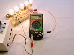
To measure currents (up the the multimeter’s 10 Amp limit), short heavy duty leads are connected to the "10A" and "COM" terminals. These five automotive light bulbs in parallel draw 9.28A from a 7-cell CP2400SCR pack (not visible).
For higher currents, up to 10A, 20A, or even 30A, depending on the meter (it will be appropriately labeled), the red lead is disconnected from the "+" terminal, and instead is plugged into the terminal labeled with the maximum Amp rating and the word "UNFUSED". The meter is set to the appropriately labeled current range (e.g. "10A"), and the leads are connected to the circuit being tested in the same way as for the low current technique.
There are a few things to keep in mind here. First, in the low-current mode, attempting to measure a much higher current (usually 0.5A or more) will blow a fuse inside the meter, after which it will no longer be able to measure low currents until the fuse is replaced. Furthermore, the meter will also have a significant effect on the circuit being measured, since the meter itself presents some electrical resistance. Thus, the measured current will not necessarily be the same as it would be if the meter weren’t there to measure it.
In the high-current mode, attempting to measure a much higher current can damage the meter, melt the test leads, or start a fire. As the "UNFUSED" label suggests, there is no fuse to protect the meter or the circuit. Furthermore, the meter leads, which are generally quite long and made with fairly thin wire, will significantly limit the current that can flow. So once again, the measured current will be different than it would be in the absence of the meter.
These losses and errors caused by the meter leads can be greatly reduced by making a set of very short, very thick (12- or 14-gage wire) leads, with gold plated plugs and heavy duty alligator clips. However, measurements will still be limited to the meter’s maximum of 10, 20, or 30 Amps, depending on the meter, which for many electric flight applications, is not enough.
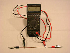
This shunt is just a length of 14 gage solid copper house wire. The length of wire between the meter’s two leads has a resistance of one milliOhm, which will give a voltage drop of one milliVolt (mV) for each Amp flowing through the wire. The meter is reading -.2mV due to stray currents picked up by the wire.
Even Higher Currents
The best way to measure higher currents is to use a shunt, which is basically a length of wire of known resistance. Remember Ohm’s law: V = I × R, or voltage equals current times resistance. The wire is installed in the circuit being tested and then the meter is used in voltage mode to measure the voltage across the wire. Dividing this voltage by the resistance gives the current flowing through the wire.
In fact, this is exactly how the meter itself measures current. There is a shunt inside the meter, and the meter measures the voltage drop across the shunt. From this it computes and displays the current.
In order to affect the circuit as little as possible, the shunt should have a very low resistance. However, if the resistance is too low, the voltage drop across the shunt will be too low for the meter to measure accurately.
For most meters, a one milli-Ohm (mΩ) shunt is suitable. This gives a reading of one milli-Volt for each Amp of current flowing through it. With the meter set to its 300mV scale, it can theoretically read up to 300A, with a resolution of 1A. In practice, the maximum will be limited by what the shunt can withstand.
A one milli-Ohm shunt is easily made using two heavy duty alligator clips and a length of 14-gage solid copper wire (taken from a scrap of house wiring). A 4.76 inch length of this wire has a resistance of 1mΩ. In practice, this will vary a bit because the wire will vary in thickness. So, make the shunt out of a 6- to 8-inch piece, and then calibrate it by using your meter to measure milli-Volts, and a second meter to measure the current. See the photos below for details. Once calibrated, mark the locations on the shunt to attach the meter leads to get accurate current readings in the future.
Battery Capacity
There often seems to be some confusion between current (measured in Amps) and battery capacity (measured in Amp-hours). I’ve seen this in e-mails, Internet forums, the modeling press, and even documentation included in model kits. Current can be measured directly, but capacity cannot. In fact, the idea for this article came about when someone wrote to me:
"I plugged the black lead into the COM socket and the red lead into the 20A socket, and set the meter to the 20A range. When I touched the leads to the battery terminals, there was a spark, and no reading."
All that this shows is that the battery can supply enough current to produce a spark, and possibly damage the meter. It doesn’t say anything about the battery’s capacity.
Capacity is a measure of how long a battery can supply a given amount of current. A capacity of one Amp-hour (1Ah) indicates that the battery can supply one Amp for one hour. This does not mean that the battery can supply only one Amp. For example, it might be able to supply 10A, but if so, it will only be able to do so for about 1/10 of an hour (10Amp × 1/10 hour = 1 Amp-hour).
Capacity can only be measured by discharging the battery at a known current and timing how long it takes to drain the battery. The known current, multiplied by the time it takes (in hours), is the battery’s capacity in Amp-hours.
The problem with this technique is that it requires a load that draws the same amount of current regardless of the battery voltage. Unfortunately, it’s not that easy to build such a load for high currents. However, for batteries in the 8V to 14V range (7 to 12 NiCd or NiMH cells) you can get a reasonably accurate estimate of capacity by using an automobile headlight, or one or more automobile brake lights, as a load.
First fully charge the battery, and then connect it to the load with the multimeter wired in-line to measure the current. Take current readings every minute and write them down. When the lights start to dim rapidly, the battery is almost dead and you can stop. Add up all the readings and divide by the number of readings to get an average current. Then, divide that by 60 (because each reading is for 1/60th of an hour) to get the capacity in Amp-hours.
Alternatively, use a device like the BattMan II Computer Controlled Battery Manager to automate this process.
So far, we’ve looked at using a digital multimeter to measure voltage and current, and how to build and calibrate a shunt to measure even higher currents. Now let’s look at how to measure resistance. We’ll see that the typical multimeter’s resistance measuring functionality is not really suitable for our use, and how to get around that.
Resistance with the Multimeter
Resistance is important to the electric modeler, but it is not often measured. Resistance is the cause of most of the losses in electric power systems. Sources of resistance include connectors, the speed control, the internal resistance of the battery and motor, and the wiring itself. There are no perfect conductors, and everything that conducts electricity has some resistance. Wherever there is current flowing through resistance, power is lost in the form of heat. Minimizing resistance is one of the keys to obtaining maximum efficiency.
Virtually all digital multimeters can measure resistance although they vary in the ranges that they provide. Most of the resistances of interest to the electric modeler are in the milli-Ohm (1/1000 of an Ohm) range, and most reasonably priced multimeters cannot measure such low resistances accurately, if at all.
Fortunately, Ohm’s law comes to the rescue. Recall that V = I × R. This can be rearranged as R = V / I. In other words, given a voltage and a current, we can compute a resistance.

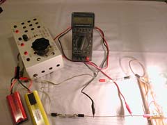
Using the left hand meter to measure the voltage difference across a connection (7.2mV), and the right hand meter to measure current (6.41A), we can compute the resistance of the connection to be 1.1 milliOhms. (0.0011 Ohms). Pins are used to tap into the wire on either side of the connection. The current is from the 7xCP2400SCR battery powering five paralleled automotive lamps (top right) through my bench top "speed control" (a large variable resistor).
For example, to measure the resistance of a connector, we can measure the voltage drop across the connector, and the current flowing through the connector. To do this, we will either need to use two multimeters, or make two separate measurements with the same multimeter.
First we’ll look at using two meters. The voltage-measuring meter is connected with its red lead on one side of the connector and its black lead on the other side. This requires access to the conductive parts of the connector. The current-measuring meter is connected anywhere in the circuit, but not between the voltage measuring leads (otherwise, we would be including the resistance of the current-meter in what we were measuring). If it’s one half of a battery connector whose resistance we are measuring, we can connect the current meter into the other half of the connector (see the photo).
To use a single meter, first measure the voltage across the connector with the meter in voltage measuring mode. Then, measure the current through the connector with the meter in current measuring mode. In this case, we can put the meter in-line with the same connector we’re measuring, because the meter wasn’t there when we measured the voltage.
Battery Internal Resistance
The internal resistance of a battery is simply the total of all the resistances of the parts that make up the battery, such as internal connections, the electrolyte, and for a battery consisting of more than one cell, the cell-to-cell connections.
Battery resistance cannot be measured using the multimeter’s resistance measuring modes. This is not because the resistance is too low (although it usually is), but rather because the way a multimeter measures resistance (passing a known current, and measuring the voltage drop) does not work if the component being measured supplies current of its own, which a battery does.
Instead, we have to rely on Ohm’s law once again, only this time, we have to measure two different voltages, and one current. First, make sure the battery is not freshly charged. If it is, use it for a while first (go fly half a typical flight), and then let it cool back to room temperature. Now measure the battery voltage, write this down, and call it V1. Next, you must measure both the battery voltage and the current flow with the battery connected to a load that causes it to draw a few Amps (an automobile headlight works well for batteries of about 8 to 14 volts). Record the voltage and the current, calling them V2 and I2.
You can now compute the internal resistance. It is the difference in voltages, divided by the current. In other words, R = (V1 – V2) / I2.
Using the Information
All these measurements we’ve made can be quite useful.
For example, if you measure the current of a power system on a regular basis, and one day it has changed significantly (more than 10%), it may indicate a problem. If the current has gone down, you may have a dead cell in your battery. If it has gone up, you may have a problem with the motor such as a bent shaft, short-circuited winding, or timing that has gone out of adjustment.
You can confirm a battery problem by measuring its voltage under load (measuring the voltage of a NiCd or NiMH battery with no load is not very meaningful, because a fully charged cell can read anywhere from 1.2V to 1.5V with no load on it). If under load, your 7-cell battery normally delivers 7V, and is now producing only 6V, it’s very likely that one cell is dead.
Measuring the voltage at the battery terminals (i.e. right where the wires are soldered onto the battery), and again at the motor terminals (at full throttle), can help pinpoint losses in the system. If the voltage is more than 0.2 to 0.5V lower at the motor terminals than the battery terminals, it can indicate either poor connectors, or an ESC that isn’t going all the way to full throttle. By measuring the voltage across each half of each connector, and across the input and output of the ESC (usually only the negative lead needs checking, as the positive lead generally passes straight through), you can narrow down where the problem is.
Note that with a brushless motor, it is not possible to measure the voltage at the motor terminals. There are three terminals, and measuring the voltage between any two of them is not meaningful, since even at full throttle, the currents are constantly being switched on and off and reversed in direction. You could make AC voltage measurements, but it is difficult to relate this to motor power.

The Astroflight WhattMeter displays current, voltage, power, and accumulated capacity all at the same time. Here we are using it to determine the internal resistance of this 6-cell 1250SCR battery. The difference in voltage (0.8V) divided by the current (9.5A) gives a resistance of 0.084 Ohms (including the cell interconnections, wires, and connectors).
Astroflight WhattMeter
Although a multimeter is very versatile, it has some drawbacks for electric flight use. The biggest of these is the relatively low current limit of most multimeters (most are limited to 10A), and thus the need for an external shunt to measure higher currents. Another problem is that some of the techniques described above work best with two multimeters, which can result in quite a mess of wires, shunts, etc.
In the mid 1990’s, Astroflight introduced the WhattMeter, which makes almost any electric flight measurement easy (except resistance measurements, but it can help with those by eliminating the need for one of the two multimeters).
The WhattMeter has a pair of input wires, which are to be connected to the power source (usually a battery), and two output wires which connect to the rest of the circuit. Once installed in a circuit, the meter simultaneously measures and displays both voltage (Volts) and current (Amps). Unlike most multimeters, the WhattMeter can measure currents up to 75 Amps. Furthermore, it also computes and displays power (Watts), which is the voltage multiplied by the current.
To top it all off, it computes capacity, which it does by multiplying current by time for successive time intervals (about one second I believe) and keeping a running total. At any given time, the capacity readout shows how many Amp-hours have been used since the power was first connected.

This GloBee tachometer can be set for 2, 3, and 4-bladed propellers. Here it is set for 3-blades, and is reading 240 to indicate 2,400 rpm (notice the "x10" label under the display). This reading is caused by the fluorescent lighting in my workshop.
I’ve had my WhattMeter since about 1997, and for most electric flight measurements, it’s all I need. Occasionally I use it in conjunction with one or more multimeters to measure resistance or track down power system problems. Astroflight now produces a MicroMeter as well, which is a WhattMeter with more precision for use at lower power levels.
Tachometer
One other useful piece of test equipment is a tachometer, which is used to measure propeller rpm. Rpm measurements can be done periodically to ensure that everything is still working at it always has, or to determine the result of making changes to the power system, such as using a different propeller or battery.
A tachometer reads rpm by "looking" at the propeller and counting how many blades go by in some time interval. The tachometer then computes the rpm (revolutions per minute) from this. In order to do this, it needs to know how many blades the propeller has, so most tachometers have a switch to select between 2-, 3-, and 4-bladed propellers.

A test stand firmly holds the motor and all the test equipment in place. Due to the optical tachometer’s sensitivity to AC room lighting, a flashlight is used as a light source instead. Make sure there are no loose objects on the bench that could be blown away by the prop wash.
The tachometer doesn’t actually "see" a propeller the way you or I do, but rather just notices that the light entering its sensor is flickering. Each flicker is counted as a blade passing by. Unfortunately, this means that the tachometer may not work well under indoor lighting. In North America, wall outlets provide alternating current (AC) that cycles 60 times per second. This causes our lights to flicker 120 times per second (once for each half of the cycle). The tachometer sees this as 120 blades per second, or 7200 blades per minute, causing it to read 3600, 2400, or 1800 rpm depending on the propeller blade setting, even if there is no real propeller in sight. This problem can be taken advantage of to ensure your tachometer is accurate.
(Outside of North America, the power cycles 50 times per second, and the tachometer will read this as 3000, 2000, or 1500 rpm.)

With the motor running, we get several useful measurements at once: 6960 rpm, 10.6A, and 6.0V, giving 65 Watts (the displayed values are rounded, which is why the displayed Watts are higher than the expected 10.6 × 6.0 = 63.6). The battery has suppled 0.13Ah of current between the time it was first connected, and this picture was taken. Using a camera is a great way to capture all these readings at once.
Some tachometers only have this problem with fluorescent lighting, but others are sensitive enough to detect the subtle flicker of incandescent lights. Two possible solutions to this problem are to perform rpm measurements outdoors like our glow-power friends do, or to use a direct current (DC) light source, such as a flashlight, in a darkened room. The room need not be completely dark because the flashlight, if pointed straight at the tachometer through the propeller arc, will "drown out" the flickering room lighting.
Once you know the propeller rpm, you can compute the propeller’s pitch speed. This is the speed that the propeller would move through the air if air were solid and the propeller were a screw. The pitch speed, in miles per hour, is equal to the rpm times the pitch (in inches) times 0.000947. For sport type models, this speed should be in the range of 2.5 to 3 times the model’s expected stall speed (which is about 4 times the square root of the wing loading in ounces per square foot). Thus, the tachometer, in conjunction with voltage and current measurements, can help you find the right propeller to suit your power system and airframe combination.
Safety
Much of the measuring we’ve discussed has involved working with operating power systems, so there are a few safety issues to keep in mind.
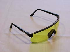
When working with motors and propellers, especially in a confined space, a pair of high-impact safety glasses is essential.
First and foremost, wear a good pair of safety glasses. Propellers can and do fail or come off the motor shaft. If this happens outdoors, injury is a possibility. Indoors, it’s almost a foregone conclusion, as the propeller or pieces of it ricochet off the walls. I’ve had it happen, but I was lucky, and now I always wear safety glasses. Keep in mind this sign we had on the wall in my high school’s chemistry lab: "Joe never used to wear his safety glasses. Now he doesn’t need them."
If you are working with running motors, make sure they are securely mounted in a test stand from where they cannot escape or even move. If a motor turns in its stand, the propeller could hit the edge of the work bench, in which case it will shatter and send pieces flying.
Next, keep all the wiring out of harm’s way. Long meter leads hanging loosely near spinning propellers are an accident waiting to happen. Keep leads away from the business end of the motor. Also be careful not to let bare alligator clips contact each other, or the motor case.
When measuring and recording many parameters at once (for example, voltage, current, and rpm), it is easy to become rushed and careless while writing all the figures down before any of them change. To keep things calm, consider using a video camera or digital camera to record all the meter readings. That way, you can concentrate on what you are doing while running the tests, and make your observations later at the comfort of your desk.
Finally, if you are using your multimeter’s high-current connectors (i.e. the "UNFUSED" one), return the positive lead to the regular connector ("+") as soon as you are done. Otherwise, the next time you use your meter for something else, like testing a wall outlet, you will be in for a big surprise. I accidentally did this while debugging our 220V well water pump circuit and ended up with very short meter probes. I also saw stars for many minutes until my eyes recovered from the flash.
Related Articles
If you've found this article useful, you may also be interested in:
- Let’s Do the Twist
- How Electric Motors Work
- More Electric Flight Terms
- Electric Flight Terminology
- Electromagnetic Interference Reduction

If you've found this article useful, consider leaving a donation in Stefan's memory to help support stefanv.com
Disclaimer: Although every effort has been made to ensure accuracy and reliability, the information on this web page is presented without warranty of any kind, and Stefan Vorkoetter assumes no liability for direct or consequential damages caused by its use. It is up to you, the reader, to determine the suitability of, and assume responsibility for, the use of this information. Links to Amazon.com merchandise are provided in association with Amazon.com. Links to eBay searches are provided in association with the eBay partner network.
Copyright: All materials on this web site, including the text, images, and mark-up, are Copyright © 2025 by Stefan Vorkoetter unless otherwise noted. All rights reserved. Unauthorized duplication prohibited. You may link to this site or pages within it, but you may not link directly to images on this site, and you may not copy any material from this site to another web site or other publication without express written permission. You may make copies for your own personal use.

Fourdan
February 25, 2009
Hello Stefan I suggest you say some words on other wattmeters having * PC link for display and recording * rpm phase sensor (more convenient that a tachometer) * Possibility of weight scale (like Medusa R) when having a bench (L shape pusher like Dr Kiwi’s one or mine) Best regards Louis
Walt Thyng
February 25, 2009
Stefan, whenever I see your name I pay attention. Your info is always great. I am now writing an electric column for the Fox Valley R/C club newsletter. You can be sure that future articles will have a lot of (properly attributed) quotes from "Measuring Up." Thanks for a great bit of work. Walt
Mr D. N Ghandhi
April 22, 2010
Sir, I shall be very happy if you will be kind enough to guide me as to how to make Source & Measure for mAmp. I want to use 4 1\2 digit L.C.D. battery operated type Module Range from 0 to 200mA. Please send me complete details if possible and help me. Thanking you, D. N. Ghandhi.
Stefan Vorkoetter
April 22, 2010
Sorry, what do you mean by “make Source & Measure”? If you want to measure mAmp with a mAmp module, there’s nothing else you need to do.
John Baum
October 08, 2012
Do you have a recommendation for a 9V transistor radio battery for use in a digital multimeter. Is it worth paying for Ultralife Li batteries?
I have a now ‘historic’ Simpson 467E. When the battery gets low, there is no ‘indicator’ but even voltage readings on batteries become erratic.
Thanks,
John
Stefan Vorkoetter
October 09, 2012
John, I think any decent alkaline 9V battery would be fine. I think the ultralife batteries are meant for high-drain devices, which your meter probably doesn’t even come close to being.