Electric Powered 3D Aerobatics
January 1, 2004 for QuietFlyer Magazine
Over the years, we’ve looked at power systems for a number of different types of aircraft, but these have fallen primarily into two categories: sailplanes and "sport" models. The latter is the average model that a typical modeler would fly at the club field (in this case, average refers to performance, not size, since everything from a 36-inch Speed 400 powered model to a 20-cell conversion of a .40 sized glow trainer falls in this category).
We’ve looked at various rules of thumb, along with some more scientific methods, for choosing power systems for such models. As a reminder, here are some of those rules:
-
Approximately 50 to 70 Watts of input power per pound of aircraft weight.
-
About 25 Amps of current to get reasonable flight time from Sub-C cells (10 Amps for models powered by smaller cells).
-
Static propeller pitch speed in the range of 2.5 to 3 times the model’s stalling speed.
-
Static thrust of about 1/4 to 1/2 of the flying weight.
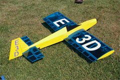
A Gary Wright Model Products E3D. This one, belonging to Marc Thompson, is powered by a brushless motor.
These rules, together with a well-designed airframe, will produce a model that can take-off from pavement or grass, fly for 7 to 10 minutes, perform some aerobatics, and land with some power remaining for a go-around if needed. This is what I mean by the term "sport". It’s a plane and performance combination for everyman.
Some pilots, however, would like more of a challenge. One way to achieve this is to enter the world of 3D aerobatics, where planes are flown in a manner that sometimes seems impossible. Loops are as small as five feet in diameter, and sometimes they are nearly square instead of round. Flight direction can change so suddenly that a hummingbird would be envious. Planes come to a halt in mid air, hanging from their propellers. And if this isn’t enough, most of this action takes place at eye level, instead of hundreds of feet in the sky.
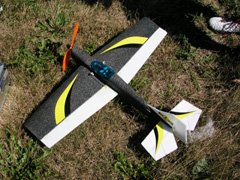
This all-foam Cobra belonging to Joe Tomasone is powered by a Razor 400 brushless motor with 5.3:1 gearbox and an 11×4.7 GWS propeller. Flying weight is 11 ounces.
Breaking the Rules
From flying our sport models, we know that this kind of performance simply isn’t possible using a plane and power system built around the rules listed above. We need to break the existing rules, and make up some new ones. Much of this has been determined experimentally, and the following are some of the guidelines that Gary Wright, designer of the low-cost yet high-performing E3D, has come up with:
-
Use a very large, relatively low pitched propeller. Static pitch speed should be about 2 times the model’s stalling speed.
-
Static thrust (at full throttle) must exceed the flying weight.
-
Don’t worry about keeping the full throttle current low (except to keep it within the limits of the motor and speed control).
A larger propeller is more efficient than a smaller one, which is one reason why gearboxes are so popular in electric models. Recall that for a sport model, we can put a gearbox on a motor, and replace the direct-drive propeller with one whose diameter is increased by the square root of the gear ratio, and whose pitch is increased by the gear ratio. For example, using a 2.4:1 gearbox, an 8×4 direct drive propeller can be replaced by a 12×10.
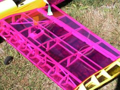
A close-up of the lightweight structure in this Super Diablotin belonging to Adam Rogozinsky. There’s not much wood in there.
A 3D aerobatic model does not require the high pitch speed of a sport model, so we can trade some of that pitch for more diameter and still maintain the same rpm and current draw. The 12×10 in the example above could become a 13×7.
Do we get anything in exchange for the pitch speed that we gave up? Yes, of course! First of all, the larger propeller will produce more thrust simply because it is producing less speed (conservation of energy). Furthermore, a larger propeller is more efficient, so it will produce even more thrust in exchange for less wasted energy (in the form of heat and noise).
Can we do even better? By increasing the gear ratio, an even larger propeller can be used. Starting with the original direct drive 8×4 example, using a 4.8:1 gearbox would suggest a 17×19 propeller. Trading some of the excessive pitch for diameter, we end up with a 19×13 propeller. This sounds large, but remember that this is still drawing the same current as the 8×4 propeller was.
But wait, there’s more! In a sport model, we limit our maximum current to get reasonably long flight times. 3D flying is very different though. There are times when full power is needed (such as when hovering), and other times when almost no power is needed (the downward leg of a square loop). Therefore, we can increase our maximum current, and by judicious use of the throttle, keep the flying times long.
The current is still limited by what the motor can handle, and the motor’s efficiency curve. Beyond a point, increasing the current produces no additional useful power, because as the current increases, the efficiency decreases faster (more power in, yet less power out). So, it’s important to know the characteristics of the motor you are using. For example, the Kyosho Endoplasma used in the prototypes of Wright’s E3D reaches maximum efficiency at about 45 Amps.
Going back to our example of a direct-drive 8×4 propeller drawing 25 Amps from a particular motor and battery, let’s see what happens if we are willing to draw a maximum of 40 Amps (assuming this is within the motor’s efficient range). This represents a 60% power increase, which will allow for approximately a 12% diameter increase. Now our 19×13 propeller can become a 21×13.
We went through a lot of gear ratio, pitch, and power changes in the preceding paragraphs. To illustrate the process more clearly, Table 1 shows a similar progression of changes applied to the Kyosho EndoPlasma motor and an 8-cell 2400SCR battery. The table starts with a direct-drive application, although that would not be typical for an EndoPlasma. It is however a starting point.
| Gear Ratio | Propeller (inches) |
Current (Amps) |
Pitch Speed (mph) |
Thrust (oz) |
|
|---|---|---|---|---|---|
| 1 | direct | 5×2 | 25 | 57 | 19 |
| 2 | 2.8:1 | 8.5×5.5 | 26 | 55 | 27 |
| 3 | 2.8:1 | 9×4 | 24 | 41 | 30 |
| 4 | 4.6:1 | 10.5×9 | 23 | 56 | 28 |
| 5 | 4.6:1 | 12×6 | 25 | 37 | 41 |
| 6 | 4.6:1 | 14×7 | 40 | 38 | 61 |
Table 1: 3D Propeller Selection Progression
Rows 2 and 4 show, for two different gear ratios, a propeller that will result in approximately the same current draw and pitch speed as the original direct-drive propeller (row 1). This would be the propeller of choice if you were simply adding a gearbox to a sport model. Notice that there is an increase in thrust, which would result in easier take-offs and steeper climbs.
Rows 3 and 5 select a propeller that trades off some pitch speed for more thrust. With the 4.6:1 gearbox, we now have over twice the thrust of the direct-drive propeller. Using these combinations on a sport model would result in good take-off performance, but a low top speed.
Row 6 shows what happens if we’re willing to increase the maximum current to 40 Amps, while keeping the pitch speed about the same as rows 3 and 5. The thrust is now much higher than most 8-cell models weigh, meaning that hovering maneuvers are possible.
Keep it Light
One of the keys to 3D flying is a greater than 1:1 thrust-to-weight ratio. We’ve seen how the judicious selection of propeller and gearbox can produce high thrusts at low flying speeds. The other way to improve the thrust-to-weight ratio is to reduce the weight. Accordingly, 3D models are generally extremely light for their size.
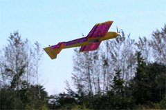
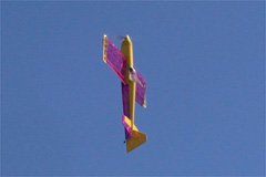
For example, the E3D with its 600 square inch wing and a 10-cell SCR battery pack weighs 56 ounces. A sport model of that size would typically weight about 70 to 80 ounces. This light weight is achieved by using built-up construction, with lots of lightening holes in any sheet balsa parts (such as ribs). Fuselages are usually stick built, and very light covering material is used throughout (transparent covering is usually the lightest, and for some reason, everyone seems to prefer yellow and purple).
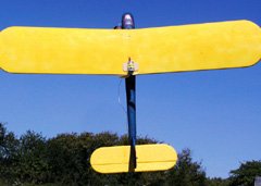
How not to power 3D: the motor is too small, there’s no gearbox, and the propeller produces only about 1/3 the plane’s weight in thrust. This is Tracy Narine’s Teddy aspiring to bigger things.
Motor Selection
In designing the E3D, Wright’s goal was to produce a 3D model that could be powered by an inexpensive power system that everyone could afford. After much calculation and experimentation, the system he ended up with consisted of a Kyosho EndoPlasma 16-turn R/C car motor, a Great Planes GD600 gearbox, a 10-tooth R/C car pinion gear (giving a 4.6:1 ratio with the GD600’s 46-tooth spur gear), 10 Sanyo CP-2400SCR cells, and a 12×8 APC Electric or 13×7.5 SonicTronics folding propeller.
Although the suggested power system works well, many modelers have taken a good thing and made it better by choosing to use a brushless motor. This has two major advantages:
-
There are no brushes to wear out and replace, which is required fairly regularly with the EndoPlasma motor at high currents.
-
The motor is more efficient, giving the same output power at lower currents, which in turn improves run-time (or, one can prop for more output power at the same current as the EndoPlasma system).
The disadvantage of course is cost, but brushless motors and speed controls are no longer as expensive as they used to be.
The Electric Advantage
Electric power is not only capable of powering a 3D model, but it has several advantages over glow power:
-
The characteristics of electric motors (more torque as you increase the load), together with the ability to use gearboxes, makes it possible to use larger, more efficient propellers. A 375 Watt (about 1/2 horsepower) electric 3D model would require a 1 to 1.25 horsepower glow engine to achieve the same performance (to make up for the smaller propeller of the glow engine.
-
An electric power system responds more quickly to throttle changes than a glow engine, making it easier to precisely control the power during maneuvers.
-
3D models spend a lot of time in other than level attitude. With electric power, there isn’t the problem of maintaining adequate fuel flow in all situations.
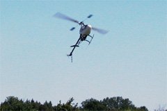
The ultimate 3D aircraft. A helicopter is where it all points to: a very high gear ratio and a huge "propeller". With its constant angle (instead of constant pitch) blades, the rotor is well suited to hovering instead of pulling a plane through the air.
In Wright’s words, "3D flying as far as the power system is concerned is all about getting maximum ‘first gear’, which really demonstrates the big advantage of electric over glow (gearing and large props)."
Acknowledgements
I’d like to thank Gary Wright (designer of the E3D) for his input to this article. I’d also like to thank Marc Thompson, Joe Tomasone, Adam Rogozinsky, Tracy Narine and Rob Campbell, whose models are the subjects of the photographs.
Related Articles
If you've found this article useful, you may also be interested in:
- Model Aircraft Power System Selection Using Your Computer: A Tutorial Introduction to MotoCalc
- Electric Flight Rules of Thumb
- Speed 400 Upgrades
- Electric Power for Sailplanes
- Fourteen Cell Fun
- Choosing an Electric Flight Power System

If you've found this article useful, consider leaving a donation in Stefan's memory to help support stefanv.com
Disclaimer: Although every effort has been made to ensure accuracy and reliability, the information on this web page is presented without warranty of any kind, and Stefan Vorkoetter assumes no liability for direct or consequential damages caused by its use. It is up to you, the reader, to determine the suitability of, and assume responsibility for, the use of this information. Links to Amazon.com merchandise are provided in association with Amazon.com. Links to eBay searches are provided in association with the eBay partner network.
Copyright: All materials on this web site, including the text, images, and mark-up, are Copyright © 2025 by Stefan Vorkoetter unless otherwise noted. All rights reserved. Unauthorized duplication prohibited. You may link to this site or pages within it, but you may not link directly to images on this site, and you may not copy any material from this site to another web site or other publication without express written permission. You may make copies for your own personal use.
DocVenki
March 18, 2008
Hi Stefan! This is a great set of articles about R/C planes. I liked the Slow flier page as well as the 3D.
Thanks a lot for these gems! Goodluck and regards, DocVenki
Darius
May 24, 2008
Great info! Thanks!