Model Airplane Electric Motor Mounting Methods
May 1, 2002 for Sailplane & Electric Modeler Magazine
In the November 2000 issue of S&E Modeler, I described a variety of battery mounting methods and mentioned the importance of keeping this significant portion of the plane’s weight from moving around. This month, I’m going to talk about motor mounting methods.
Although in most models the motor is not as heavy as the battery, it is extremely important that the motor does not move. Furthermore, unlike the battery, the motor is actually doing something, and must be held firmly in place despite any desire on its part to shake itself loose and leave the airplane. The methods which follow are ones that I’ve found to be effective for my models. There are of course many more methods that could be used.
Requirements
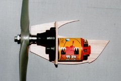
Here a Kyosho Atomic Force car motor is mated to a Master Airscrew 3:1 gearbox through a bulkhead in a partially built motor nacelle.
Like the battery, the motor should be kept away from the receiver and servos to reduce the possibility of electrical noise interfering with proper operation of the radio.
Furthermore, the motor requires cooling, just like the battery. In planes where the motor is operated only intermittently (for example, rapid climbs to altitude, followed by long glides), cooling is less important, but in any plane where the motor operates more-or-less continuously, cooling is essential. Excessive heat can weaken the motor’s magnets, rendering it less efficient and less powerful. Ferrite brushed motors suffer the most from this problem. Brushless motors are more tolerant, since the windings are on the outside and the heat doesn’t need to go through the magnets to escape. ("Outrunner" brushless motors, such as those from Model Motors, don’t have this advantage.)
Finally, the motor mounting method must be able to cope with sudden forces, such as a fast zero-to-full-throttle startup, which will try to twist the motor right out of its mounting.
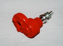
The raised mating flange on the Master Airscrew gearbox makes it possible to mount it through a bulkhead.
Some Mounting Methods
What follows are some of the mounting methods I’ve used successfully on my own models.
Through the Bulkhead
My electrified Sig Riser 100 is powered by Kyosho Magnetic Mayhem motor, mated to a Master Airscrew 3.5:1 gearbox, turning a 15×12 folding prop. I installed a front bulkhead/former, with the motor on one side and the gearbox on the other. With most gearboxes, this is a bad idea, because it can make it difficult to keep the gears properly aligned and meshed. However, the MA gearboxes have a raised mating flange, and it’s possible to cut a bulkhead that fits around this flange. By using 3/32" plywood, and sanding it down slightly, the bulkhead will not interfere with the gearbox-to-motor mating at all.
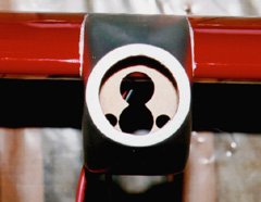
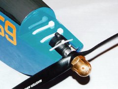
A front view of the nacelle shows the shape of the hole cut in the bulkhead to fit the gearbox flange.
Since the bulkhead is an integral part of the plane, this mounting method does a great job of holding the motor and gearbox rigidly in place. Installing and removing the motor in the plane is easy, since the motor and gearbox are just screwed together.
The likely reason the MA gearboxes have a raised flange is so that the gearbox doesn’t cover the front cooling inlet holes of the 05 sized ferrite motors that the gearbox is designed for. When mounting to a bulkhead as described, the bulkhead will block these holes. In electric sailplane models, this is not a big issue, because cooling air blowing over the surface of the motor is usually sufficient for the typically short motor runs used. For continuous operation, the bulkhead should probably have slots in it to allow cooling air to reach the front inlets. In my twin-motored Sig LT-25, I left the wing mounted motor nacelles open at the back to expose the motor casing to air, but I may need to provide additional cooling.
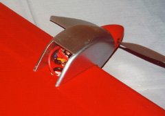
The finished nacelle is open at the back to allow some cooling. It should probably be open on the bottom too, or have a cooling air intake scoop.
The main drawback of this method is that it only works if the shape of the plane’s nose (or nacelles) will accommodate the motor/gearbox combination, with its offset output shaft. The other drawback is that it really only works with the Master Airscrew gearboxes, although there may be other gearboxes with a similar flange that I’m unaware of. If it’s not possible to make the gearbox contact the motor the way it would in the absence of a bulkhead, don’t use this method.
Back of the Firewall
Many motors used in electric flight have convenient bolt holes on the front surface. This makes it easy to mount these on the back of a firewall using the appropriate number of bolts (technically, a firewall separates an engine from the rest of an airplane, so with the motor mounted behind it, it’s not really a firewall any more).
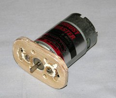
A Great Planes Goldfire motor bolted to the back of a plywood firewall. Notice the cooling holes, which line up with holes in the front of the motor.
Most 05 sized ferrite motors, including "can" motors and R/C car motors, have a pair of mounting holes on one-inch centers. Usually, these holes are threaded for 4-40 or 3mm bolts. Use bolts that are no more than 1/4" longer than the thickness of the firewall, or you’ll risk interfering with the motor’s armature, or cracking its magnets.
For direct-drive can motors, the firewall should have cooling holes drilled into it to let air enter the motor’s front cooling inlets. I’ve found that the shell of a dead can motor makes a great template for marking all the holes. Start by drilling the hole for the front bearing (which protrudes from the motor). Insert the empty motor shell, and use a sharp pencil from the inside of the shell to mark all the cooling and mounting holes. Then use a drill, knife, and sandpaper to make matching holes in the firewall.
The Great Planes GD-600 gearbox also has holes on one-inch centers, although these are not threaded. For my newly reincarnated Fred’s Special, I threaded the gearbox holes using a 4-40 tap, and then bolted the gearbox to the back of the firewall in much the same way as I would a direct drive motor. Since the motor itself is attached to the gearbox and is out in the open (the bottom front part of the fuselage is completely open), there was no need to make additional holes in the firewall.
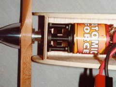
A Kysosho Atomic Force motor and Great Planes gearbox, bolted to the back of the firewall of my redesigned Fred’s Special. The bottom front of the fuselage remains open, providing the motor, battery, and speed control with plenty of cooling.
I recently removed the geared Magnetic Mayhem motor from my Spectra, and replaced it with an Aveox F10 Light brushless motor/gearbox combination. This is designed to bolt directly to the back of a firewall, so I had to redesign the nose one more time to accommodate it. The Spectra kit as it comes from the factory could easily accept this motor with just a new, sturdier firewall, but I’d already reworked the nose to take the geared Magnetic Mayhem.
Dowels or Rails
The traditional method of mounting a glow engine involves two longitudinal rails. The engine is then bolted to the tops of these rails. Often, the two rails are part of a one piece aluminum or plastic engine mount which can be bolted directly to the firewall. Similar methods can be used for electric motors.
An easy way to make a pair of rails for an electric motor is to install two dowels through the firewall and a secondary former a few inches behind the firewall. In my twin Speed 400 Ace Pacer electric conversion, I drilled dowel holes directly into the leading edge of the wing, to a depth of about 2", and just epoxied the dowels right into the foam. The spacing should be such that the motor rests on them, with most of the motor above the tops of the dowels.
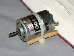
This Speed 400 motor is attached to the dowels with a nylon cable tie. The dowels are set directly into a glassed foam wing.
There are a number of ways to fasten the motor to the rails. For very small motors in low powered airplanes, rubber bands often suffice. In a nose-first crash, the rubber bands have some give to them, which often saves the motor from damage. For slightly more powerful motors, I’ve had great success using nylon cable ties. Just be sure that the cable ties are pulled as tight as they will go.
Other fastening methods include steel hose clamps, strips of metal formed around the motor and screwed to the rails, or motor-specific clamshell mounting rings (which also double as motor flux rings, reducing rpm and increasing torque).
A rail-mounted motor can have excellent cooling, since the front, back, and sides, are open. Cooling is limited only by the airflow entering the cowling. On some models, such as my twin Pacer, there may be no cowling at all, with the motor out in the open.
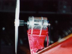
Another Speed 400 motor held by nylon cable ties, this time on the motor pylon of my 75% scale scratch-built Ace PuddleMaster. You can’t get better cooling than this!
Pylon Mount
Mounting a motor on a pylon is generally only done in flying boats, although one could construct a pylon-like mount that extended from the front of a wing or fuselage for a normal sport model. If old-timer models can have pylon-mounted wings, why not pylon mounted motors too?
Unlike the original 05-sized Ace PuddleMaster, which mounted the motor to a bulkhead held over the wing by two vertical posts, I opted for a more streamlined design when I scratch-built a scaled-down Speed 400 powered version of this plane. I constructed a pylon from 1/8" light plywood, and glued two hard balsa rails along the top edge of it, one per side. I then wrapped a piece of sandpaper around an old 400 motor, and used this to sand a concave surface to set the motor on. I smeared some silicone sealant onto the surface and let it dry, just to make it non-slippery. Finally, I set the motor on top, and held it on using nylon cable ties through holes in the pylon.
This arrangement provides the ultimate in cooling. 95% of the motor is in the breeze, and none of the holes are covered. I routinely fly this model for 12 minute flights with a 7×1100 pack, and the motor is barely warm after landing.
A Bit of Everything
In my Great Planes SlowPoke, I use a Kyosho Endoplasma 16-turn R/C car motor and Master Airscrew 3:1 gearbox. I made extensive modifications to the kit’s built-up glow engine mount. The electric motor ends up under the engine mount, protruding rearward through a circular hole in the firewall. The offset gearbox sticks out above the engine mount, with the prop adapter ending up in exactly the location that a glow engine’s prop mount would be. Two rails on the bottom of the engine mount plate keep the motor from moving side to side, and nylon cable ties keep the motor pulled firmly up against the plate. A smaller cable tie over the top of the gearbox keeps the assembly from moving forward due to the prop thrust.
Two large cable ties bind the motor to the bottom of the SlowPoke‘s glow engine mount. A thinner cable tie keeps the whole assembly from moving forwards.
Many Other Ways
These are just a few of the many possible motor mounting methods. Any method that holds the motor securely under all the conditions it will encounter in flight, and provides adequate cooling, is suitable. Other factors to keep in mind when designing a method include ease of removal or maintenance and proximity to radio equipment. Although the number of designed-for-electric kits is increasing, many electric models are still original designs or conversions of glow designs, so motor mounting continues to be an issue. Careful thought and planning can go a long way towards producing a satisfactory installation.
Related Articles
If you've found this article useful, you may also be interested in:
- Always Ready to Fly
- ARF Upgrades
- Conversion from Glow to Electric
- Scale Electric Airplane Design
- Building and Installing Skis on Your R/C Plane
- Electric Aircraft Battery Mounting Methods

Buy Stefan a coffee! If you've found this article
useful, consider
leaving a donation to help support
stefanv.com
Disclaimer: Although every effort has been made to ensure accuracy and reliability, the information on this web page is presented without warranty of any kind, and Stefan Vorkoetter assumes no liability for direct or consequential damages caused by its use. It is up to you, the reader, to determine the suitability of, and assume responsibility for, the use of this information. Links to Amazon.com merchandise are provided in association with Amazon.com. Links to eBay searches are provided in association with the eBay partner network.
Copyright: All materials on this web site, including the text, images, and mark-up, are Copyright © 2024 by Stefan Vorkoetter unless otherwise noted. All rights reserved. Unauthorized duplication prohibited. You may link to this site or pages within it, but you may not link directly to images on this site, and you may not copy any material from this site to another web site or other publication without express written permission. You may make copies for your own personal use.
Chris Edgar
October 01, 2010
Steve
Helpful but doesn’t cover the outrunner. And wrt the pylon mounting option, is there a preferred thrust line to be used when setting up?
Stefan Vorkoetter
October 01, 2010
Steve, it would have covered outrunners if they had existed at the time I wrote the article. With pylon mounting, you generally want a bit of up-thrust (as opposed to the down-thrust often used with nose-mounted motors). Because the thrust is above the centre of gravity, the plane tends to pitch down a bit when you apply power. The up-thrust compensates for this.
Jimmy Demello
December 04, 2011
Very useful information. I like the dowel mount idea, simple and lightweight.
Rick Martz
March 10, 2012
Any hints for how to connect tiny wires? When I try to strip insulation the wire breaks.
Stefan Vorkoetter
March 10, 2012
Rick, what sort of wires, and what are you using to strip the insulation? If they are enamel-covered wires (i.e. motor windings), then the best way to get the insulation off is to carefully scrape it off with an X-acto knife. If they are plastic-covered, use an electronic technician’s wire stripper, adjusted for the appropriate wire size.
Nrg Steering Wheel
August 27, 2024
The method is limited by whether the shape of the plane’s nose or nacelle can accommodate the motor and gearbox combination, especially with its offset output shaft. If the dimensions and shape don’t align, this method may not be feasible. This approach primarily works with Master Airscrew gearboxes. If other gearboxes do not have a similar flange or configuration, they may not be compatible with this method. It’s important to ensure the gearbox can connect properly to the motor.