Fourteen Cell Fun
December 1, 2001 for Sailplane & Electric Modeler Magazine
So you’ve been flying electric R/C for a while, and have decided to move beyond the common 7-cell power system. Or, perhaps you want to fly larger planes so you’ll fit in better at the local glow field. Like many beginning electric flyers, you may have purchased a 7-cell charger designed for R/C cars, and you don’t want to spend the money for a charger that can handle larger battery packs. You are in the infamous "7-cell trap". (I’m not exactly sure of the origin of this phrase, but I think Dereck Woodward might have had something to do with it.)
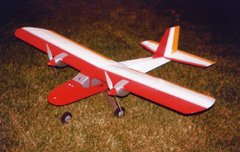
This is a Sig Kadet LT-25, converted to twin-electric power and tricycle landing gear. Kyosho Atomic Force motors turn APC 10×7 electric propellers through Master Airscrew 3:1 gearboxes. A pair of 7xRC2000 packs provides the power.
Well, there is a way out that doesn’t involve blowing the budget on big motors and big chargers. You probably already have two or more identical 7-cell battery packs. All you need is two 7-cell capable motors, and a 14-cell capable speed control, and you have a power system for a 14-cell plane.
Choosing a Plane
What makes a good 14-cell plane? In short, twice a good 7-cell plane. This does not mean twice the wing span, but rather twice the weight and volume. Wing span and other linear dimensions will only increase by a factor of 1.26 (the cube root of 2). Wing area will increase by a factor of 1.59 (the cube root of 2 squared).
Given these figures, you can choose a suitable subject for 14-cell electric power based on your experiences with good 7-cell models.
Let’s start with my favorite example, a 48 inch span, 432 square inch area, 48 ounce 7-cell sport model. A 14-cell plane with equivalent performance would span 60 inches, have 686 square inches of wing area, and weigh 96 oz. An example of a plane that comes close to these specifications is the Sig Kadet LT-25, which spans 63 inches, has 724 square inches of wing, and usually weighs around 100 oz with 14 cells.
Motor Choices
There are a number of choices for powering a 14 cell model, besides the obvious choice of a single suitable motor.
Twin
The easiest to choose power system for a 14-cell model is two of whatever works well in the equivalent 7-cell model, with minor changes to the propeller size to adjust for the higher stall speed (and hence higher required pitch speed) of the larger model.

Figure 1. Wiring diagram for a 2-motor, 2-pack power system. The wires marked yellow can be any color so long as you can distinguish them from the red and black.
For example, if a 7-cell model flies well with a Kyosho Atomic Force motor with a 3:1 gearbox and an 10×7 propeller, an equivalent 14-cell twin would fly well on two such systems. Without going into the math, the propeller pitch should be increased by 12%, and the diameter decreased by 3%, to increase the pitch speed while keeping the rpm and load on the motor the same. So, the 10×7 propeller should be changed to a 9.7×7.8 (in real life, the closest available size, namely 10×8, would work fine).
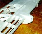
To make the LT-25 into a twin, I extended the leading edge sheeting by one rib bay, and attached nacelles made from 1/4 inch thick balsa.
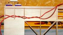
This view of the motor wiring inside the LT-25 wing shows the twisting used to reduce radiated noise.
The two motors, the speed control, and your two 7-cell batteries, should be wired in series, as shown in figure 1. The speed control must be capable of handling 14 cells, and the same current that the 7-cell single motor system drew. Each motor should have interference suppression capacitors installed on it, and each should have its own Schottky diode (with the banded end towards the positive motor terminal).
The power wires to the motors should be twisted, to reduce radiated noise that could otherwise interfere with the R/C system.
Single Propeller Twin
If you don’t wish to build a twin-engined model, but still want to take advantage of a pair of low-cost motors, you can use two motors to drive a single propeller through a dual-gearbox such as the one produced by Anthem Metal Products.
If you purchase a dual-gearbox with the same ratio as a single gearbox, the rule for choosing a propeller is very simple. Pitch should be increased by 12% from that of the propeller used with one motor and 7-cells, and diameter should be increased by 16%.
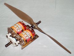
An Anthem 3:1 dual gearbox, with two Kyosho Atomic Force motors, and APC 12×8 electric propeller. This will be going into a Sig MidStar-40, powered by two 7-cell packs.
For example, if a given motor with a 3:1 single gearbox flies a 7-cell plane well with a 10×7 propeller, two such motors on a dual gearbox will fly the equivalent 14-cell plane with an 11.6×7.8 prop. In real sizes, 12×8 would be a good choice.
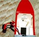
Two pairs of Sermos connectors serve to connect the two 7-cell packs in series, regardless of the motor configuration.
The wiring for this configuration is identical to that of two motors driving separate propellers. The instructions provided with the Anthem dual-gearbox suggest that the two motors be installed so that their cogging is out of sync. In other words, when one motor is stopped in one of its natural resting spots (every 60 degrees for a motor with a three-pole armature), the other should be exactly between two such spots. This will reduce the cogging of the combined motors, and according to Anthem, will increase motor longevity.
Because the propeller shaft comes out of the gearbox from the end opposite the motor shafts, the motors do not have to be reverse timed as they usually would for use in a single-stage gearbox.
I had difficulty obtaining the gearbox (I think I bought the last one New Creations R/C had left), but you can build your own from R/C car gears. You just need to ensure that the gears are large enough that they’ll span the distance between the motor shafts. For a 3:1 ratio, a pair of 14-tooth 32-pitch pinion gears, and a 42-tooth 32-pitch spur gear are appropriate.
One Motor
The traditional approach to 14-cell models (or any models) is to use a motor suitable for that number of cells. For example, an Astro 25G motor/gearbox combination can turn a 12×8 propeller on 14 cells. You no longer get the financial benefit of using two inexpensive motors, although you can still use separate 7-cell packs, and hence your 7-cell charger. You also get the advantage of a motor that is specifically designed for electric flight, very efficient, and more durable.
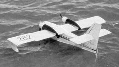
Robert Pike’s Canadair CL-215 water bomber uses a pair of Astro 05G geared motors, 10×8 props, and 20 cells. 10×7 props and 21 cells (three 7-cell packs) would also work well. Wing span is 76 inches, area is 800 sq.in, and wing loading is 23 oz/sq.ft.
There are also some less expensive ferrite motors that can operate on 14 cells, such as a Graupner Speed 700 BB Turbo 9.6V motor, with a 2.5:1 gearbox and 11×8 propeller. These motors are typically heavier and much less efficient than the more expensive cobalt or brushless motors, or a even pair of R/C car motors such as the Atomic Force.
Charging
The two 7-cell packs used in a 14-cell power system can be charged separately, and then used together during one flight. There may be very slight differences in the state of charge of the two packs, but this will typically not be much more than the differences one would find between cells within a single (unmatched) pack.
If one pack runs out first, the drop in power will be immediately apparent. Just cut the throttle and land. If you attempt to continue to fly at full throttle, you could damage the pack that ran out, as it will become reverse charged while the other pack continues to discharge. The same thing can happen if you are using a single 14-cell pack that was charged all at once, except that only one or two cells are likely to run out first. This means the drop in power will be less noticeable, and cell reversal more likely.

A great example of what can be achieved using inexpensive power systems. Ivan Pettigrew’s Lancaster bomber spans 103 inches, with 1300 sq.in of wing area, and weighs 13 lb. Power is four Master Airscrew 05 ferrite motors with 3:1 gearboxes, 13×8 3-blade propellers, and 24 cells.
BEC Considerations
Most 7-cell models make use of the battery-eliminator circuit (BEC) feature of the speed control. Unfortunately, most speed controls that can handle 14 cells either do not have BEC, or cannot provide BEC from that many cells. This means that you’ll need to use a separate receiver pack. The good news is that the added weight of a 4-cell 600mAh receiver pack is much less significant in these larger models, especially if using the new smaller, lighter NiMH AAA cells.
Three or More Motors
The principles discussed so far apply to larger models as well. Three 7-cell packs can power a 21-cell model, and four packs can power a 28-cell model. I’m not aware of any gearboxes that allow three or four motors to turn a single propeller, so you would probably end up with a three or four-motored plane. With 28 cells, you could use two separate dual gearboxes, with two motors for each of two propellers.
The following table lists the scale factors for scaling a 7-cell design up to various multiples of 7 cells. In all cases, it is assumed that the battery packs and motors are wired in series. An example of a suitable model for three 7-cell motors is the Sig Kadet LT-40.
| Cells | Motors | Linear Scale | Area Scale | Propellers | Pitch Scale | Diameter Scale |
|---|---|---|---|---|---|---|
| 14 | 2 | 1.26 | 1.59 | 1 | 1.12 | 1.16 |
| 14 | 2 | 1.26 | 1.59 | 2 | 1.12 | 0.97 |
| 21 | 3 | 1.44 | 2.08 | 3 | 1.20 | 1.26 |
| 28 | 4 | 1.59 | 2.52 | 2 | 1.26 | 1.12 |
| 28 | 4 | 1.59 | 2.52 | 4 | 1.26 | 0.94 |
Related Articles
If you've found this article useful, you may also be interested in:
- Model Aircraft Power System Selection Using Your Computer: A Tutorial Introduction to MotoCalc
- Electric Flight Rules of Thumb
- Speed 400 Upgrades
- Electric Powered 3D Aerobatics
- Electric Power for Sailplanes
- Choosing an Electric Flight Power System

If you've found this article useful, consider leaving a donation in Stefan's memory to help support stefanv.com
Disclaimer: Although every effort has been made to ensure accuracy and reliability, the information on this web page is presented without warranty of any kind, and Stefan Vorkoetter assumes no liability for direct or consequential damages caused by its use. It is up to you, the reader, to determine the suitability of, and assume responsibility for, the use of this information. Links to Amazon.com merchandise are provided in association with Amazon.com. Links to eBay searches are provided in association with the eBay partner network.
Copyright: All materials on this web site, including the text, images, and mark-up, are Copyright © 2024 by Stefan Vorkoetter unless otherwise noted. All rights reserved. Unauthorized duplication prohibited. You may link to this site or pages within it, but you may not link directly to images on this site, and you may not copy any material from this site to another web site or other publication without express written permission. You may make copies for your own personal use.
Abdulhai Bhati Falcon
September 21, 2010
I LIKE THIS