Demystifying Gearing and Gearboxes
March 1, 2000 for Sailplane & Electric Modeler Magazine
How often have you heard, "Geared electric power systems are for slow aircraft." This is a myth, and I’m going to show you why. Gearing is useful for many types of aircraft, from slow flying sailplanes, to fast moving aerobatic models. First we’ll look at what gearing actually does, and then we’ll examine how to apply it to our models. Throughout this article, I will use the term gearing and gearbox to include belt drives as well.
What Does Gearing Accomplish?
Gearing reduces the shaft rpm of an electric power system (it can be used to increase rpm too, but I know of no cases where this has been done for an electric aircraft). Power is torque times rpm, and neglecting mechanical losses in the gearbox, the output power of a geared system will be the same as a direct drive system. If the rpm goes down, the torque goes up. More torque means the motor can turn a larger propeller, and larger propellers are more efficient.

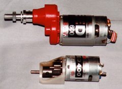
Two typical single stage gearboxes. At the top is a Master Airscrew gearbox for Speed 600 size motors, which comes in 2.5:1, 3:1, and 3.5:1 ratios, and features ball bearings on the output shaft. At the bottom is a Modelair-Tech GB-50 for Speed 400 size motors. This is a simple, low-cost gearbox with a 2.14:1 ratio, metal gears, and an easily replaceable 1/8" output shaft.
You might ask, why not just put the larger propeller directly on the motor shaft? After all, the extra load would slow down the motor, and torque would increase. The problem is that the increase in torque will cause a corresponding increase in current, and an even greater increase in power lost as heat. You will get some torque for your lost rpm, but you’ll also get a lot of heat, which is just wasted power. Generally, direct-drive power systems already use the largest propeller that the motor can safely and efficiently handle with a given number of cells.
For example, a Speed 600 8.4V motor on 7 cells can turn an 8×4 propeller at about 19 Amps with 60W lost as heat, or 9×5 at about 25A and 90W lost, with reasonable longevity and about 50% to 60% efficiency. But if you put a 12×8 prop on the same motor, current shoots up to about 40A, nearly 200W of heat are given off, and efficiency drops to about 30%. The motor will probably not even last a minute at these levels before something melts or burns.
By using gear or belt reduction, the motor can turn that large propeller slowly, while the motor itself continues to operate at the higher rpm at which it is more efficient. To sum things up, gearing down a motor lets you use a larger, more efficient propeller, while keeping current and power losses under control, and remaining within the efficient operating range of the motor. Another way of looking at it is that gearing allows you to match a given propeller to the characteristics of a given motor.
Propping for a Given Gear Ratio
If you already know what gear ratio you want to use (for example, you have a certain gearbox sitting around in your parts bin), you’ll need to select a propeller to suit the motor with that gear ratio. It turns out that this is very simple to do if you know of a suitable direct-drive propeller for your motor.
The power it takes to turn a propeller is given by the following formula, taken from Bob Boucher’s Electric Motor Handbook:
Power = D4 x P x N3
D, P, and N are the diameter, pitch, and rpm respectively. I haven’t included any units here (e.g. inches, Watts, etc.) because we’d have to introduce a fudge-factor to adjust for these, and that doesn’t matter for our purposes.
Now, recall that the output power of a geared system is about the same as that of a direct-drive system if the motor is turning at the same rpm in both cases. If the motor is turning the same rpm, then the propeller in the geared system will be turning slower by factor equal to the gear ratio. Furthermore, let’s assume we want the same pitch speed (pitch times rpm, the theoretical speed at which the propeller screws itself through the air if there were no slippage). Since the propeller is turning slower, we have to increase the pitch to compensate, and this increase would also be by the gear ratio.
So, we can now write:
D14 x P x N3 = D24 x (P x G) x (N / G)3
D1 is the diameter of the direct-drive propeller, D2 is the diameter of the geared propeller, and G is the gear ratio (for example, 2.5 if the gear ratio is 2.5:1). We can solve this equation to determine D2, and after all is said and done, we get the very simple formula:
D2 = D1 x G½
In other words, the diameter of the geared propeller should be the diameter of the direct-drive propeller times the square root of the gear ratio. And as we discussed above, the pitch of the geared propeller should be the pitch of the direct-drive propeller times the gear ratio.
This method will give you a propeller that will cause the motor to perform approximately the same way it did with a direct-drive propeller. If you will be using the motor in an application where that direct-drive system would have been suitable, then the calculated propeller is a good one to try first when you switch to gearing. On the other hand, if the direct-drive propeller was ill-suited to the original application, you should use the calculated propeller as a starting point for experimenting, going to higher pitch and lower diameter for a higher speed application, or vice-versa for a lower speed application.
As an example, let’s look at our Speed 600 8.4V motor with an 8×4 direct-drive propeller, and assume you have a Master Airscrew 2.5:1 gearbox you wish to use with it. The diameter of the new propeller you should use would be 8 x 2.5½, which is 12.65 inches (13 inches is close enough). The pitch of the new propeller is simply 4 x 2.5 = 10 inches. So, this motor and gearbox combination should run well with a 13×10 prop.
What has this gained us? Well, the original 8×4 propeller would have run at approximately 10,000 rpm, and produced 17oz of static thrust. The geared propeller would turn at only about 4,000 rpm, but produce about 27oz of static thrust. Input current, motor heat dissipation, and efficiency would remain about the same.
This begs the question, what has it cost us? The answer is, very little. Some power (usually between 5% and 10%) will be lost in the form of noise and heat due to gearbox inefficiency. The gearbox and larger propeller adds weight to the model. Most importantly, because we multiplied the pitch by more than the diameter, we’ve ended up with a high pitch-to-diameter ratio, and such a propeller is inefficient at low speed (there goes the myth that gearing is only good for low speed models). But, you can easily get around that by going to a bigger, lower-pitched propeller if that’s what your application needs.
Gearing for a Given Propeller
We can attack the problem of gearing the other way around as well. Instead of picking a propeller to suit a given gear ratio, you can pick the gear ratio to suit your propeller. For example, if you were building a scale model, you might want to use a scale diameter propeller. All we have to do is turn our formula around, solving for the gear ratio:
G = (D2/D1)2
Suppose we’re building a 1/12th scale de Havilland Twin Otter. The full sized plane has a 10ft diameter propeller, so we’ll want a 10in diameter for our model. Let’s assume we want to use a pair Kyosho Magnetic Mayhem motors wired in series, running on 16 cells (hence 8 each). Assume we want to operate at about 26A, and that we know that a Magnetic Mayhem on 8 cells will turn a 7×4 propeller at about 26A. Our desired gear ratio for a 10in propeller will be (10/7)2, which is very close to 2, meaning a 2:1 gear ratio would be ideal. The pitch of our 10in propeller should then be 4 x 2 = 8 inches. So a 2:1 gear ratio with 10×8 propellers would be a good first choice. The pitch is a bit high for a relatively slow plane like the Twin Otter, so a 10×7 might be a better choice, giving a slight reduction in current (and hence longer motor runs).

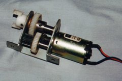
A two stage industrial gearbox. Although this particular gearbox wasn’t designed for model aircraft use, the principle of operation is the same. I purchased several of these at a surplus store, and plan to adapt them for e-flight some day (by removing a lot of metal and using hollow shafts, all in the name of saving weight).
Types of Gearboxes
The majority of gearboxes are single stage. There is a pinion gear which is fastened to the motor shaft, either by friction, glue, or a grub screw. An output gear, or spur gear, is fastened to the output shaft. On some gearboxes, the spur gear is actually molded onto the output shaft, and cannot be removed. Examples of single stage gearboxes are the standard Astroflight gearboxes, the Astroflight superboxes, the Master Airscrew gearboxes for Speed 600 motors, and the Modelair-Tech GB-50 gearbox for Speed 400 motors. Almost all gearboxes have a metal pinion gear, but inexpensive gearboxes usually have a nylon output gear. Most gearboxes have straight-cut gears (meaning that the teeth run parallel to the axis of the gear), but a few, most notably the newer Astroflight ones, have helical-cut gears (the teeth spiral slightly around the perimeter of the gear). This makes for a quieter, more efficient gearbox.
Single stage gearboxes usually have the effect of reversing the direction of rotation of the output shaft. This means that either the motor must be wired to run backwards, or you must use a left handed propeller. The output shaft is also offset from the motor shaft by the sum of the radii of the two gears. There are a few single-stage gearboxes where the spur gear is actually a ring, and the pinion gear runs on the inside of it (inner-driven), resulting in no reversal of rotation, and a more centrally located output shaft.

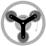
Front-view cross-section of a planetary gearbox. The pinion gear, center, drives the three planet gears, which both rotate around their own centers and revolve as they roll along the inside of the fixed outer gear. As the planet gears revolve, the planet carrier (the black Y-shaped piece) goes around with them. The output shaft, not shown, is attached to the center of the planet carrier.
A dual stage gearbox, such as the Graupner Speedgear series, basically consists of two single stage gearboxes in a row. The motor drives the pinion gear, which turns an intermediate gear. This gear is fastened to the same shaft as a second pinion gear, which in turn drives the final output gear. Each stage provides some reduction in speed, and each stage reverses the direction of rotation, so the final output direction is the same as that of the motor shaft. Furthermore, with two stages, it’s very easy to have the output shaft be close to or exactly in line with the motor shaft.
A planetary gearbox consists of a central pinion gear (the sun), surrounded by three intermediate gears (the planets). These three gears are all fastened to a common carrier. Surrounding the three planet gears is a toothed ring. As the sun gear turns, the planet gears rotate about their own axes, and in so doing revolve around the sun gear. The output shaft is connected to the carrier that holds the three planet gears, and this ends up rotating in the same direction as the pinion gear. The output shaft is also exactly in line with the motor shaft. The most well known planetary gearboxes are the Robbe Planeta series, sold in North America by Aveox.

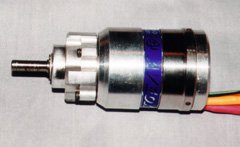
A Robbe Planeta gearbox mounted on the front of an Aveox brushless motor. Note the compact size of the gearbox and the in-line output shaft. This gearbox is really an integral part of this motor. The motor cannot be used without it.
A belt drive consists of a small toothed pulley that is attached to the motor shaft, and a larger toothed pulley attached to the output shaft. A toothed rubber belt runs on the two pulleys. Like two stage gearboxes, belt drives do not reverse the direction of rotation. One drawback to a belt drive is that it puts a strong sideways load on the motor shaft, so you must use a motor with ball bearings. Simple bushings would wear out too quickly. Belt drives have been made very popular by Tom Hunt of Modelair-Tech.
Timing Considerations
If you will be using a gearbox that changes the direction of rotation of the output shaft, it is important that you re-time the motor for reverse rotation. Simply hooking it up backwards is not sufficient. If you’ve purchased a motor and gearbox combination already assembled, for example from Astroflight, Aveox, or Maxcim, this timing will already have been done for you. If you’ve purchased the motor and gearbox separately, you’ll need to re-time it yourself.
Some motors, such as Speed 600 can motors, have fixed timing. These are best used with a belt drive (if the motor has ball bearings), or a two stage or inner-driven single stage gearbox so that you can run the motor in the normal direction of rotation.
Other motors, such as the Magnetic Mayhem, also have fixed timing, but come in forward and reverse versions. If you’re using one of these, purchase the one that fits your application.
The majority of model aircraft motors have adjustable timing. For these motors, follow the manufacturer’s instructions to adjust the timing appropriately for the direction it will be turning in. If there are no timing instructions, the following will get you close enough.
Run the motor from a low voltage (3 or 4 cells), making sure the motor is running in the direction it will be running when it’s installed in your aircraft. Monitor the current while you rotate the end-bell to get the minimum current. This is neutral timing. Now, rotate the end-bell opposite the direction that the shaft is turning until the current increases by 10% of the current you expect to be running it at.
Conclusion
Hopefully I’ve convinced you that gearing is not for slow planes, but rather just a means of using a larger, more efficient propeller with a small motor. The proper choice of motor, gear ratio, and propeller will let you get the most out of your model.