Flit! A Speed 280 Four Channel Aerobat
June 30, 2000 for Sailplane & Electric Modeler Magazine
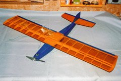
After having a lot of fun with my Sydney’s Special, a scaled-down Speed 400 sized version of Vernon Williams’ Fred’s Special, I wanted something a bit more aerobatic and less trainer-like. I also wanted to see just how small a full-house (four channel) aerobat could reasonably be made, so I decided to design something. What I ended up with is the 9.1oz (260g), 29.3 in (74.4cm) span Speed 280 powered Flit.
![flit v. To move or fly rapidly and lightly; dart; skim. [ from the Old Norse flytja, to remove or move ] flit v. To move or fly rapidly and lightly; dart; skim. [ from the Old Norse flytja, to remove or move ]](http://www.stefanv.com/rcstuff/../quiet/flit/photo0.jpg)
flit v. To move or fly rapidly and lightly; dart; skim.
[ from the Old Norse flytja, to remove or move ]
Don’t let the Speed 280 motor mislead you. This is no park flyer, and definitely not a slow flyer. At over 50W/lb and with a level-flight top speed of about 40mph, Flit is fast for a plane this size. With 4-channel control and a flat semi-symmetrical wing, Flit can do anything the larger pattern ships do, only apparently faster. Imagine the flight of a sparrow compared to that of a larger bird like a hawk. However, the low wing loading and shoulder wing location give Flit enough stability to not require nerves of steel and lightning reflexes to keep it in the air.
So, if you’re a Speed 400 sport flier wanting to move up (or is that down?) to something a bit more exciting, or a seasoned pattern pilot who wants a plane you can almost keep in your pocket, then Flit is for you.
Specifications
| Plane: | Flit |
|---|---|
| Model Type: | 4-channel aerobatic |
| Pilot Skills: | Intermediate |
| Wing Span: | 29.3 in. (74.4 cm) |
| Airfoil: | Eppler 205 |
| Length: | 20.8 in. (52.8 cm) |
| Weight: | 9.1 oz. (260g) as built |
| Wing Area: | 152.5 sq.in. (9.84 sq.dm) |
| Wing Loading: | 8.6 oz./sq.ft. (26.4 g/sq.dm) as built |
| Functions: | Throttle, rudder, elevator, ailerons. Requires three sub-micro servos and a micro-receiver. |
| Construction: | All built-up, balsa, hardwood, and ply |
| Power: | Graupner Speed 280 motor, APC 5.5×4.5 propeller, 7x270AA cells. |
Construction
Flit is a straightforward all-wood plane, built in more-or-less traditional ways. Being small, it doesn’t take a lot of wood. To keep the weight down, use the lightest stiff wood you can find. For adhesives, I used thin and medium CA. Let’s start with the wing.
Wing
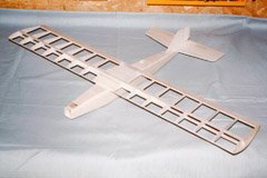
This is truly a one-piece wing. The leading edge, spars, and trailing edge are each a single piece. There is no wing joiner.
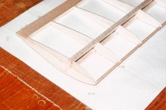
Make a rib template out of cardboard (the back of a pad of paper is ideal). Pin the template onto a 1/16" balsa sheet, and cut around it with a sharp knife. Repeat 18 times. Take four of the ribs, and trim 1/32" off of the top and bottom of each (use the template as a cutting guide). Also trim the alignment tabs off these ribs. These will be the center section ribs.
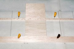
Cover the wing plan with wax paper, and pin the 3/4×3/16" trailing edge stock to the board. Mark the center section rib locations on the front of the trailing edge. Cut some 1/32" balsa, with the grain running spanwise, for the bottom sheeting between the trailing edge and spar. Glue it to the trailing edge, and pin down. Next glue the 1/4×1/8" balsa bottom spar up against this, and pin the spar down at various points along its length. Mark the center rib locations on the spar as well. Cut more 1/32" balsa to complete the bottom sheeting well past the front of the leading edge, and glue and pin it in place.
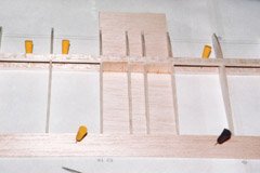
Install the four center section ribs, making sure they are square to the sheeting. Use the marks you made on the trailing edge and spar as guides. Glue them only behind the spar for now. Next install and glue the remaining 14 ribs, making sure they are square to the work surface. When all the ribs are in place, trial fit the top spar, and then glue it in place.
Cut to fit and glue in the center section shear webs next. The grain should run vertically, and the pieces should fit snuggly between the ribs. The shear webs should stop 1/32" below the top of the spar.
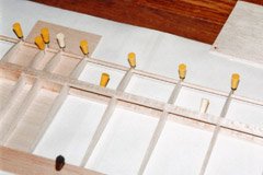
Pins to the right of each rib keep them from bending as the leading edge is pushed into place from the left.
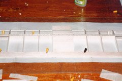
Insert a pin into the building surface against the right hand side of the front of each rib, being careful not to block the leading edge hole. Push the 1/8" hardwood dowel through all the ribs from the left, turning it as you go (it helps to sharpen one end first). Once the dowel is in place, ensure all the ribs are straight, and apply a drop of thin CA at the back of each rib/dowel junction.
Pull the bottom leading edge sheeting up to meet the dowel, and glue it to the dowel and ribs. Next, cut the two pieces of 1/32" top sheeting to fit, and glue them in place. Install the remaining shear webs next. These will be taller than the center section ones.
Using a razor saw, carefully cut off any excess leading edge, spar, and trailing edge material at the two wing tips. Unpin the wing from the board, and cut off the rib alignment tabs. Install the 1/16" sheet balsa tips. These stick straight out from the wing. Install a triangular brace to keep the tips square to the wing when you shrink the covering.
Finally, carefully slice the ailerons from the trailing edge stock. Use a razor saw for the ends, and many passes of a very sharp knife along their length. Be sure to cut perpendicular to the bottom surface. Sand a single bevel into the aileron leading edge for later top-hinging with tape. Glue 1/16" ply control horns to the ailerons with medium CA where shown. Apply a fillet of white glue around the base of the control horn.
Check all the joints, and add a drop of medium CA wherever needed. The framed up wing should weigh about 1oz (28g). It will seem rather flexible at this point, but it stiffens up immensely when covered.
Fuselage
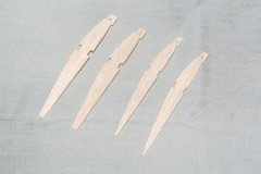
Cut out the two fuselage sides, and install 1/8" square balsa stringers along the entire bottom, front, and top edges. (Obligatory Warning: be sure to make a left and right side!) The stringer under the wing follows the flat part of the wing; it does not curve up at the leading edge. Install a second piece of 1/8" square balsa behind the piece at the nose.
All the stringers are there primarily to provide a gluing surface for the top sheeting and something to sand away when rounding the corners, not for strength. Therefore, it is not necessary that they be one piece from front to back. I started a separate piece at each corner in the fuselage. Use very light balsa for these (I cut them from a 1/8" contest-grade sheet using a Master Airscrew balsa stripper).
Formers F2 and F3 are made from 1/8" balsa ply. I don’t know if you can buy this or not, but I make it by gluing two layers of 1/16" balsa to each other with the grains running at right angles. I use aliphatic resin (white glue) for this, spread thin on both pieces, which are then clamped together between two flat blocks of wood. The top of F2 is a separate piece of 1/8" square hard balsa.
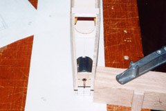
Glue F2 and F3 in place on the right fuselage side, ensuring they are square to the side. Glue the left side to this, making sure the two sides line up (otherwise you’ll end up with a twist when you pull the tail together).
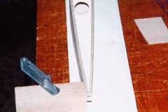
Fuselage sides brought together at tail. The block is keeping it straight until the top sheeting is in place.
Put the fuselage upside down on the bench, and sheet the bottom from F2 to F3 with 1/16" balsa with the grain running across the fuselage. Turn the fuselage the right way up, and pin it to the board over the plans. Bring the tail ends together, making sure the joint is centered. Clamps and blocks of wood help here. When everything is aligned, apply thin CA to the joint. When cured, reinforce with a drop of medium CA.
Make firewall F1 from 1/16" ply. I found that the easiest way to do this was to clamp the material between two 1/4" thick hardwood pieces, and drill the holes through the hardwood and plywood together. The hardwood serves to keep the ply from splintering around the drill bit. Once the holes are drilled, remove the ply from between the blocks, and draw the shape of F1 around the holes. Cut it out with many passes of a sharp knife. You should end up with a firewall with round holes, crisp edges, and no splinters.
Bring the two sides of the nose together, lined up with the plan, and glue F1 between them, to the backs of the second 1/8" square pieces you added earlier. The front of F1 should be 1/4" back from front of the fuselage.
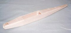
Sheet the top of the fuselage in front of and behind the wing, turn it over, and finish sheeting the bottom. All the sheeting should have its grain running across the fuselage. When done, sand all the edges round except where the wing and stabilizer go. Aim for about a 1/4" radius edge.
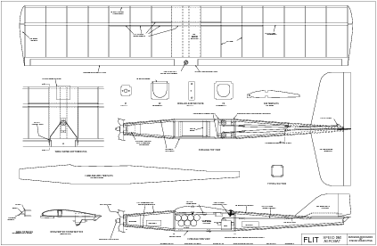
Cut a cooling air inlet in the top sheeting just behind F1, as shown on the plans. Using a razor saw and knife, cut the cooling air and aileron pushrod exit holes under the wing, as shown on the plans. Cut a 1.35" long cross-brace from 1/4×1/8" balsa, and glue it between the top stringers under the wing where shown. Then cut a piece of 1/4×1/16" balsa 1.6" long and glue it under this and to the bottoms of the stringers.
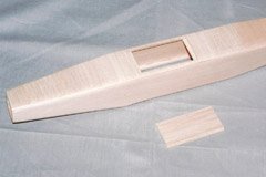
Turn the fuselage upside down and cut out the battery hatch. Using the cut out piece as a template, cut a new piece for the hatch with the grain running lengthwise (or, reinforce the inside of the hatch with a piece of 1/32" balsa with the grain running lengthwise). Glue 1/4×3/32" cross pieces over the ends of the hatch opening. With the fuselage upside down, the hatch should be able to rest on these pieces and be flush with the fuselage.
Cut two pieces of 1/4" square balsa to the width of a servo, and glue them to the fuselage sides and the front of F3. Cut another piece, 1.6" long and glue it between the fuselage sides to serve as the forward servo mounting rail (position it appropriately for the size of servo you’ll be using). Harden the servo blocks and rails with thin CA.
Make the rear wing hold-down plate out of 3/32" ply, and drill only the two outermost holes for now. These are to allow a screwdriver to pass through for servo mounting. Glue the plate under the stringers, snug against the front of F3, with the holes to the back.
The completed fuselage should weigh about 1/2oz (14g).
Tail Feathers
The horizontal and vertical stabilizers, the elevator, and the rudder, are all cut from 3/32" contest-grade balsa. Try to select a fairly stiff sheet. Round the stabilizer leading edges, and bevel the elevator and rudder leading edges for tape hinging. Install 1/16" ply control horns as described for the ailerons.
The tail feathers should weigh about 0.2oz (6g).
Covering
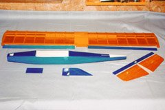
I covered the prototype with transparent Solarfilm. I find that this material is a good compromise between ease-of-use (it already has an adhesive on it, and requires no further finishing) and lightness (it’s much lighter than most other iron on film coverings). Any light-weight covering material should be fine though.
Before covering the horizontal stabilizer, mark where it meets the fuselage, and don’t cover that area. I prefer this approach over cutting away the covering later since I won’t accidentally weaken the structure by cutting into the wood. Likewise, don’t cover the top of the fuselage and horizontal stabilizer where the vertical stab will be glued on.
Leave the part of the wing that will be inside the fuselage (about the middle 1 1/4") uncovered too, as you still need to glue things to it.
After covering, hinge the ailerons, elevator, and rudder using your favorite hinge tape (living in Canada, I used clear hockey tape, cut to 3/8" width; it lasts for ever, and costs about a buck a roll).
Final Assembly
Put the wing on, making sure it’s on straight, and tape it in place. Turn the model upside down, and glue the 1/8" thick front wing hold-down tab to the bottom of the wing. The grain should run front-to-back, and the tab should be tight against the underside of the top rail of F2.
Turn the model right side up, and drill a hole through the trailing edge and rear wing hold-down plate with a #43 drill bit. Drill at right angles to the top surface of the wing. Remove the wing, and enlarge the hole in the wing to clear a 4-40 bolt (a 3/32" drill bit is about right). Reinforce the wood around the hole by squirting some thin CA in the hole (redrill afterwards if necessary). Thread the wing hold-down plate with a 4-40 tap.
Bolt the wing to the model with a 4-40 nylon bolt. Use a fiber washer under the bolt head to spread the pressure a bit. Trial fit the horizontal stabilizer, and sand the stabilizer seat area as necessary so that it’s level with respect to the wing. Glue the horizontal stab in place with medium CA.
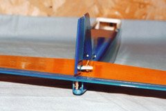
Next, glue the vertical stabilizer onto the horizontal stab and fuselage, ensuring that it’s at right angles to the horizontal stab, and lined up with the fuselage center line. Apply a fillet of medium CA along both sides of the joint.
Hinge the hatch at the front using a short piece of hinge tape. At the back, screw a cut-off servo arm into the wood behind the hatch, so that it can be swiveled to keep the hatch shut. The screw should be tightened enough that this "latch" won’t move on its own. Apply thin CA to the screw from inside the fuselage to harden the wood and keep the screw from loosening.
Power System Installation
The Graupner Speed 280 motor has two nice mounting holes in the front. The only problem is that these holes are not threaded at all. To rectify this, bend open the tabs that hold the end-bell on the motor, and carefully disassemble the motor (be sure to mark the magnets so you get them back in the same way). Enlarge the holes using a #43 bit, and then thread with a 4-40 tap. Clean out any metal shavings, reassemble the motor, and bend the tabs back down so they firmly hold the end-bell in place. Alternatively, you might find some #4×1/8" sheet metal screws you could use to hold the motor in place.
Attach the speed control to the motor, shortening the wires as necessary (I have about 3/4" of wire between the motor and ESC). Use a light-weight speed control with a BEC that can handle three servos, and at least 5A of motor current. I used one of my own design, but with the tabs on the MOSFET and BEC regulator partly sawn off to save space.
Slide the motor/ESC combo into the nose of the plane, and fasten using 1/8" 4-40 bolts. Attach an APC 5.5×4.5 Speed 400 prop using a Graupner Speed 280 prop adapter (I recommend balancing the prop first). If you built everything exactly right, the prop adapter should bottom out with the back of the prop just a hair’s breadth away from the front of the fuselage. Drill a small hole in the bottom of the fuselage to insert an Allen key.
Make up a battery pack from seven Sanyo 270AA or Panasonic 30AAR/FT (300mAh) cells, in a three-over-four arrangement. For connectors, I used 4-pin Deans plugs with two pins per wire, as any other kind (Sermos, Deans Ultra Plugs, Astroflight, etc.) are far too large for this plane.
Equipment Installation
Make up the pushrods as shown on the plan. Put a bend in the wires where they terminate on the wooden pushrods, and insert this into a hole drilled in the wood. Wrap the ends with thread and fix in place with thin CA. Make a Z-bend at the servo ends, and leave the control surfaces ends straight for now.
Install the elevator and rudder servos, and temporarily hook them up to a receiver. Turn everything on and make sure the servos are centered. Slide the pushrods in place, connect them to the servo arms, and install these on the servos. With the rudder held straight, mark where the pushrod wire passes the hole in the rudder horn, cut the wire about 1/4" longer than this, and make a downwards L-bend at the mark. Using a 45W soldering iron with a pointed tip, apply a blob of solder to the end of the wire (it helps to have cleaned and sanded the wire beforehand). Repeat the process for the elevator pushrod.
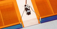
Cut a hole to fit your aileron servo in the wing’s bottom center section sheeting. Apply a strip of masking tape down one side of the servo, across the bottom, and up the other side, and insert the servo into the hole with the output shaft end towards the front of the wing. CA the taped part of the servo to the wing sheeting.
Make up aileron pushrods as shown in the plan and photos. With the ailerons at neutral, the pushrods should go approximately through the middle of the cooling air exits you cut in the fuselage sides.
Balancing
At this point, all that’s left to install is the battery and the receiver. I’ve left these until last because you’ll need to experiment with the optimal location to properly balance the model. The desired balance point is right under the spar. I ended up with the battery up against the back of F2, and receiver behind F3 as shown on the plan. The opening in F3 is large enough to push the receiver through.
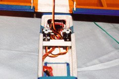
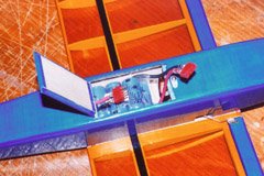
A view into the under-wing area, showing the Hitec HS55 rudder and elevator servos, and the Feather receiver behind them.
The battery is held with Velcro® glued to 1/8" foam rubber, which in turn is glued to the under surface of the wing. The connection between the ESC and battery ends up right under (with the plane upright) the battery, and the hatch, pressing on the connectors, helps hold the battery against the Velcro.
The receiver, a Hitec HS55, is mounted with self-adhesive Velcro pieces. Route the antenna through the fuselage and out the back under the elevator.
Final Adjustments
Adjust the control throws as follows: elevator up and down 1/8", rudder left and right 1/2", and ailerons up and down 1/8".
Flitting
Out of respect for those of you who always read the flying part first, I wrote this part first too. The first flight took place on a calm, sunny, Sunday evening during the half hour between dinner and chores. I had two packs of 300mAh Panasonic NiCd cells ready to go, so I went flying.
The launch was uneventful, and Flit climbed out faster than I expected. I flew with the ailerons coupled to the rudder, ailerons on low rate, and elevator on high rate (in case it was way out of trim). At full throttle, Flit exhibited a slight nose-up tendency, which a few clicks of down trim took care of. After sorting that out, I throttled back to about 2/3, and proceeded to tear around the sky for four minutes. I found the controls a bit sensitive (especially the elevator), but quickly got used to it. I tried a loop from a slight dive, and was rewarded with a nice 50′ or so circle. Flit is very sleek, and doesn’t lose much speed during such maneuvers. Next, I switched off the aileron-rudder coupling, and tried a roll, which was nice and axial (given my limited aerobatic skills so far).
One thing that struck me is how quiet this plane is. I only fly electric, but this is by far the quietest plane I’ve ever flown. The low power level (about 30W) and well balanced prop both contribute to this lack of noise. Even flying by myself in a field in the country, I could barely hear the model. In the company of glow planes, or even other electrics, Flit would be impossible to hear.
When the battery started to run low, I cut the throttle, made a few S-turns, and came in for a landing. The wind-milling prop is an effective airbrake, so there was no tendency to glide on forever in ground-effect. Our field is a bit rough (it’s a hay field, and I’m writing this in early spring), so Flit came to a stop quickly when it came into contact with the short scruff. Since it’s so light though, no damage was done.
This plane gets small fast, and at any significant distance, orientation is a bit of a problem. There’s no dihedral, and the fuselage is very thin. With the transparent covering on the wings, it’s sometimes hard to tell if the fuselage is on top or underneath. I found I had to keep it in very close to feel comfortable flying it, which is good training for me, since I usually tend to fly too high and far away.
Because of Flit‘s small size, its apparent speed is very high, so things happen quickly. On the other hand, Flit is completely predictable. It goes where you point it, and is not the least bit twitchy. But ask for a roll or a turn, and things happen immediately. Watching it fly is like watching a movie of a larger pattern plane, played back at double speed. I wonder if that means I can learn aerobatics in half the time?
Related Articles
If you've found this article useful, you may also be interested in:
- Sig LT-25 Twin Electric Conversion
- GravelMaster – A Cheap Tough Speed 400 Fun Plane
- Electrifying the Great Planes SlowPoke
- Trials and Tribulations of an Ace Pacer Electric Conversion
- Sig Riser 100 Electric Conversion
- A Speed 400 PuddleMaster Flying Boat
- Spectra-V: A Modified Great Planes Spectra

If you've found this article useful, consider leaving a donation in Stefan's memory to help support stefanv.com
Disclaimer: Although every effort has been made to ensure accuracy and reliability, the information on this web page is presented without warranty of any kind, and Stefan Vorkoetter assumes no liability for direct or consequential damages caused by its use. It is up to you, the reader, to determine the suitability of, and assume responsibility for, the use of this information. Links to Amazon.com merchandise are provided in association with Amazon.com. Links to eBay searches are provided in association with the eBay partner network.
Copyright: All materials on this web site, including the text, images, and mark-up, are Copyright © 2026 by Stefan Vorkoetter unless otherwise noted. All rights reserved. Unauthorized duplication prohibited. You may link to this site or pages within it, but you may not link directly to images on this site, and you may not copy any material from this site to another web site or other publication without express written permission. You may make copies for your own personal use.



Julietzulu Jys
June 24, 2011
Wah….. bagus sekali. terima kasih untuk informasinya……
Woow…..good, thanks for your information….
Gabriel Doudna
January 12, 2015
Wow, you just build planes from scratch… I’m still flying my first plane (RTF out of the box)! These designs are very clever.
Gabriel Doudna
January 12, 2015
I could never build a plane as well as you can!