Build a USB Powered AA NiMH and NiCd Battery Charger
February 5, 2007
I’m always complaining about all the chargers and wall warts I need to carry with me when going on a trip. This project, which can charge a pair of AA Nickel Metal Hydride (NiMH) or Nickel Cadmium (NiCd) cells using a laptop’s USB port for power, arose to address part of that problem. (By the way, if you want to lighten your laptop load, take a look at the MoGo Mouse.)
Any USB port can supply 5V at up to 500mA. The USB standard specifies that a device may not use more than 100mA until it has negotiated the right to use 500mA, but apparently no USB ports enforce that requirement. This makes the USB port a convenient source of power for devices such as this charger.
There are commercially available USB AA charging solutions available, but they each have some drawbacks:
-
The USBCell is a 1300mAh AA NiMH cell with a removable top that allows it to be plugged directly into a USB port. No separate charger is needed. Unfortunately, the cell capacity is very low (most NiMH AA cells are 2500mAh these days), and each cell requires its own port.
-
There is a two cell USB powered AA charger available, sold under a variety of names, but it charges at a very low 100mA rate. The distributor calls it an “overnight charger”, but at 100mA, a 2500mA cell would take about 40 hours to charge (40 instead of 25 due to the inefficiencies of charging at low currents).
-
I found a 2/4 cell charger that can be powered by a USB port, auto adapter, or wall wart, but it is as large as the wall charger I’m trying to replace. Different ones can be found here and here, but these take 10 to 12 hours to charge 2500mAh cells.
[December 2007 Update: Sanyo has introduced a USB powered charger for their Eneloop batteries. This charger has none of the drawbacks listed above, and will charge a pair of 2000mAh cells in about 5 hours, or a single cell in half that time. Although designed for Eneloops (see my review), it will work with regular NiMH cells as well. Watch for a review on this site soon.]
The charger in this project is designed to charge two AA NiMH or NiCd cells of any capacity (as long as they are the same) at about 470mA. It will charge 700mAh NiCds in about 1.5 hours, 1500mAh NiMHs in about 3.5 hours, and 2500mAh NiMHs in about 5.5 hours. The charger incorporates an automatic charge cut-off circuit based on cell temperature, and the cells can be left in the charger indefinitely after cut-off.
Specifications
This charger has the following specifications:
- Size: 3.8″L x 1.2″W x 0.7″H (9.7cm x 3.0cm x 1.5cm).
- Cells: Two AA, NiMH or NiCd
- Charging Current: 470mA
- Charge Termination Method: Battery Temperature (33°C)
- Trickle Current: 10mA
- Power Source: Desktop, Laptop, or Hub USB port
- Operating Conditions: 15°C to 25°C (59°F to 77°F)
The Circuit
The heart of this charger is Z1a, one half of an LM393 dual voltage comparator. The output (pin 1) can be in one of two states, floating or low. While charging, the output is pulled low by an internal transistor, drawing about 5.2mA of current through Q1 and R5. Q1 has a beta of about 90, so about 470mA will flow through into the two AA cells being charged. This will fully charge a pair of 2500mAh cells in just over 5 hours.

USB powered AA charger schematic.
During charging, R1, R2, and R4 form a three-way voltage divider which yields about 1.26V at the non-inverting input of Z1a (pin 3, Vref).
TR1 is a thermistor that is in direct contact with the cells being charged. It has a resistance of 10kΩ at 25°C (77°F), which varies inversely with temperature by about 3.7% for every 1C° (1.8F°). R3 and TR1 form a voltage divider whose value is applied to the inverting input (pin 2, Vtmp). At a temperature of 20°C (68°F), TR1 is about 12kΩ, which makes Vtmp about 1.76V.
Once the cells are fully charged, the charge current will literally go to waste, in the form of heat. As the cell temperature rises, TR1’s resistance drops. At 33°C (91°F), the resistance will be about 7.4kΩ, which makes Vtmp about 1.26V, which equals the Vref voltage.

Battery voltage versus time. The cells are full when the voltage peaks, and the charger shuts off shortly thereafter.
As the temperature rises above 33°C, Vtmp will become less than Vref, and the open-collector output of Z1a will float high. Therefore, the current flowing through R5 is greatly reduced, as it is now limited by R1, R2, and R4. As a result, the current flowing through Q1 and the cells is reduced to a 10mA trickle charge rate.
Also, because R4 is now connected to +5V through R5 and Q1 instead of being held at 0.26V by Z1a, the Vref voltage changes to about 2.37V. This guarantees that as the cell temperature drops, the charger won’t turn back on. In order for Vtmp to reach 2.37V, TR1 would have to reach about 20kΩ, corresponding to a temperature of about 6°C (43°F), which should never happen in a room temperature environment.
Z1b is the other comparator on the LM393 chip, and a close look at the schematic reveals that it’s performing the same comparison as Z1a. Instead of driving the charging transistor however, it drives an LED that indicates that charging is in progress. R6 limits current to the LED to about 10mA. By running the LED from its own comparator (which is on the chip whether we use it or not), the LED current has no effect on Vref.
Finally, C1 is there to ensure that charging starts when a pair of cells is inserted. With no cells in place and the charger off, C1 has about 1.9V across it (5V – 0.7V – Vref). As soon as the second of two cells is inserted, the positive side of C1 is suddenly forced down to the battery voltage (about 2.4V). This immediately forces the negative side 1.9V lower than this, to about 0.5V. Since this is connected to Vref, Z1a’s output goes low, causing charging to start. After a few milliseconds, C1 adjusts to the new voltage difference imposed by R1, R2, and R4 on one side and the cells on the other, and no longer affects the circuit.
Construction
The circuit is best built on a printed circuit board. Refer to my article on the subject, Making Excellent Printed Circuit Boards. Here is the printed circuit layout:
. Click to enlarge.")
Copper side. Actual size is 3.8" x 1.2" (9.7cm x 3.0cm). Click to enlarge.
Begin by installing all the resistors and the capacitor. The resistors should be installed lying flat. Install LED1, being sure to orient it so that the negative terminal is the one connected to pin 7 of Z1b.

Component placement diagram. Click to enlarge.
Install Z1 next, ensuring that pin 1 (indicated by a small dot or identation on one corner of the IC) is oriented as shown in the placement diagram. If you wish, use a socket for Z1.
Transistor Q1 is mounted on a small heatsink. First bend the leads back 90° just where they start to narrow. Don’t bend them too sharply or they might break. Insert Q1 into its lead holes, and slide the heatsink underneath. Hold everything in place with a clamp while soldering the leads. With the clamp still in place, drill the hole for the heatsink bolt.

Charger with all electronic components installed. Note that there is space under Q1 for the heatsink. The board area where the battery holder will go has been scuffed up to aid adhesion.
Installing the battery holder is the next step. I used a 2-cell holder made by cutting the two outer cell positions off of a side-by-side 4-cell holder. You can of course just buy a 2-cell holder, but none was available when I went to the parts store. My approach has the additional advantage that the cells are easier to insert and remove, because the sides of the holder don’t curve inwards over the cells.
Before installing the holder, remove a ¼” long section of the centre divider to make room for the thermistor. Also solder some leads to the cell holder terminals. Glue the holder in place on the circuit board, flush with the sides and ends of the board. When the glue has dried, drill through the TR1 holes in the board to make matching holes in the battery holder. If you did everything carefully, these two holes should be right on the centre line, where you removed the section of divider.
Insert the thermistor through the holes, and then put a pair of AA cells in the holder. From the copper side, push up on the thermistor so it is in firm contact with the cells, and then solder it in place. Then remove the cells, and connect the battery holder leads to the holes marked B+ and B- on the placement diagram.

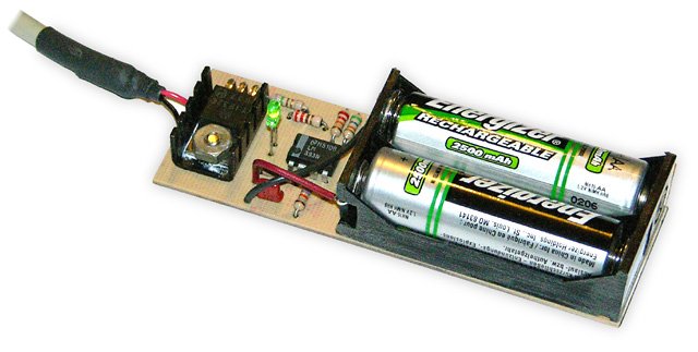
The completed charger with one cell in place. The 2-cell holder was made by cutting the outer positions off of a 4-cell holder. Notice how the thermistor is installed so as to make physical contact with the cells being charged. A small heatsink keeps Q1 cool.
The last step is to connect a USB power cable. Either buy a cable, or cut one off of a discarded USB device such as a broken mouse. Cut the cable to the desired length, and strip about 1″ of the outer covering off the end. Roll back the shielding, and find the +5V and GND wires. These will generally be red and black respectively. Strip and tin the ends of them, and solder them to the USB+5V and USBGND terminals of the charger.
Testing
Before connecting the charger to a power source, inspect your work carefully. Be sure all the components are oriented correctly (specifically Q1, LED1, Z1, and the battery holder).

For initial tests, I used a USB hub for power. A pair of #11 hobby knife blades between the cells and the contacts let me hook up a voltage monitor.
For initial tests, I suggest you use a powered USB hub. By using a hub, you ensure that the charger is not drawing power from your computer, since a defect in the charger could damage the power source. Note however that most powered hubs won’t output any power unless the hub is connected to a computer. Alternatively, you could use a regulated 5V power supply, temporarily connected to the +5V and GND traces on the circuit board.
With power applied, check that the LED is off. If it is on, use a 330Ω resistor to short out TR1 for an instant (this makes the circuit think the cells have gotten extremely hot). If the LED doesn’t extinguish, there’s something wrong.
With the LED off, measure the voltage between GND and Vref (pin 3 of Z1). This should be approximately 2.37V. It can be a bit more or less depending on the exact supply voltage and the variation in resistor values. Also check the voltage at Vtmp (pin 2). At room temperature, this should be in the range of 1.60V to 1.85V, depending on the temperature.
Now insert a pair of matching AA NiMH cells, preferrably ones that are partially or fully discharged. As soon as you insert the second cell, the LED should light up. Measure the Vref voltage again; it should now be about 1.26V. Vtmp may also have changed a little bit, due to the supply voltage drop caused by the load placed on the power supply.
The charger is now charging and the voltage at the battery terminals should be increasing. After a while, the rate of increase should slow down. As the cells reach about 75% charge, the rate of increase will speed up again. Finally, when the cells reach 100% charge, the voltage will start decreasing, and the cells will start to get warm. 15 to 20 minutes later, the charger should turn off. If the cells get uncomfortably warm and the charger has not shut off, there’s something wrong.
It’s also worth measuring the charge current. The easiest way to do this is to insert two thin conductive strips, such as brass shim, separated by an insulator, between one cell and a battery holder contact. Then connect an ammeter to the two strips, so that the charging current flows through the meter. The meter should read somewhere between 450 and 490mA. If it’s any higher, you will be exceeding the USB current supply specification, since the charger itself uses an additional 10mA (primarily for the LED).
If the measured current, I, is too high or too low, replace R5 with a different value resistor according to the following formula:
R5 = 1.6 x I
Use the nearest standard value. For example, if you measure a current of 510mA, replace R5 with an 820Ω resistor. If the measured current was 420mA, use a 680Ω resistor.
Enclosure
At the time I wrote this, I had not yet constructed an enclosure for this circuit, but plan to do so in the near future, since the bare board is not robust enough to throw into the laptop bag when going on a trip. The enclosure will be made from 1/16″ plastic or aircraft plywood for the sides and bottom, with a translucent plastic panel over the circuitry. The battery compartment will be left open. A strain relief will prevent the USB leads from breaking off where they attach to the board. For cooling, I plan to drill holes in the sides and top in the heatsink area.
Using the Charger
Using the charger is easy. Just plug it into a USB port and insert the two cells you want to charge. When the LED extinguishes, charging is complete. Approximate charge times are as follows:
| Cell Type | Charge Time |
|---|---|
| 700mAh NiCd | 1.5h |
| 1100mAh NiCd | 2.5h |
| 1600mAh NiMH | 3.5h |
| 2000mAh NiMH | 4.5h |
| 2500mAh NiMH | 5.5h |
It is important that the two cells being charged are of the same type and at the same level of discharge. If the cells are mismatched, one will become fully charged before the other. When it reaches 33°C, the charger will shut off. If the second cell needs more than about 200mAh more than the first cell, it will not have reached a full charge.

This charger, with a suitable enclosure, is ideal for use on trips, using a laptop to power the charger. The laptop should be plugged in to avoid running down its battery.
In general, if two cells are used together in a single device (digital camera, GPS, etc.), then they will remain in sync, and can be charged together.
When charging is completed, the charger will switch to a 10mA trickle charge. This is sufficient to overcome the cells’ natural self-discharge rate, but low enough that the cells can be left in the charger indefinitely. However, do not leave the cells in the charger unless the charger is plugged into a powered-up USB port. Otherwise, the cells will supply power to the circuit and be drained in the process.
When using this charger with any computer, make sure that the computer is not set to go into a power saving mode that turns off power to the USB ports. If this happens, charging will stop, and the cells being charged will discharge. When using a laptop as a power source, it’s best to plug in the laptop’s power supply, since the charger uses a significant amount of power, and will probably take longer to complete than the laptop battery will last.
If powering this charger from a USB hub, be sure to use a powered hub. A non-powered hub will not be able to deliver enough current to the charger, since it must share the 500mA coming from the computer with the ports in the hub (typically four). The extra cable length also tends to reduce the voltage reaching the charger.
Charging AAA Cells
If the springs in the battery holder are long enough, the charger can also be used to charge a pair of AAA cells. However, it is then necessary to insert shims between the cells and the sides of the battery holder to ensure that the cells remain in contact with the thermistor. Only charge modern AAA cells, having a capacity of 700mAh or more.
Parts List
Some parts can be obtained at Radio Shack, but larger electronic supply houses like Digi-Key are more likely to stock all the parts needed.
| Part | Description |
|---|---|
| R1 | 56kΩ ¼W, 5% resistor |
| R2 | 27kΩ ¼W, 5% resistor |
| R3 | 22kΩ ¼W, 5% resistor |
| R4 | 47kΩ ¼W, 5% resistor |
| R5 | 750Ω ¼W, 5% resistor |
| R6 | 220Ω ¼W, resistor |
| TR1 | 10kΩ @ 25°C thermistor, approx. 3.7%/C° NTC Radio Shack #271-110 (discontinued†) |
| C1 | 0.1µF 10V capacitor |
| Q1 | TIP32C PNP transistor, TO-220 case |
| Z1 | LM393 dual voltage comparator IC, DIP |
| LED1 | Red, green, or yellow LED, 10mA |
| Other | 2-cell AA battery holder USB cable Small heatsink |
†Note that the Radio Shack thermistor has been discontinued. Although I have not tried any of them, there are other similar thermistors available, such as the Vishay #2381 640 54103 (Digi-Key #BC2298-ND). The temperature coefficient is slightly different (about 4.6%/C°), but over the range we’re interested in, is close enough. Using this thermistor, the cut-off and turn-on temperatures would be about 32°C (89°F) and 10°C (50°F) respectively.
Alternatively, you can use the resistor values below with the Vishay thermistor to raise the cut-off temperature back to 33°C, while lowering the turn-on temperature to 3°C (37°F).
| Part | Alternative Resistor Values to use with Vishay #2381 640 54103 Thermistor |
|---|---|
| R1 | 82kΩ ¼W, 5% resistor |
| R2 | 33kΩ ¼W, 5% resistor |
| R3 | 27kΩ ¼W, 5% resistor |
| R4 | 39kΩ ¼W, 5% resistor |
I have not tested this combination, but the values were computed using the same program that I used to compute the values that were used with the Radio Shack thermistor. Do not mix and match values from this table with those listed above. If you change any of the values to those in this table, change all of them.
If anyone finds an alternative source for the Radio Shack thermistor, please let me know.
![]()
![]()
![]()
![]()
![]()
![]()
![]()
![]()
![]()
![]()
Related Articles
If you've found this article useful, you may also be interested in:
- BattMan II: Computer Controlled Battery Manager
- High Speed NiCd Charger for Electric R/C
- Low Cost Thermal Peak Detection NiCd Charger
- MusicRack – A Digital Sheet Music Display System
- A Compact Home-Made Raspberry Pi Tablet
- Make a Dual-Boot IDE Cable
400 Comments

If you've found this article useful, consider leaving a donation in Stefan's memory to help support stefanv.com
Disclaimer: Although every effort has been made to ensure accuracy and reliability, the information on this web page is presented without warranty of any kind, and Stefan Vorkoetter assumes no liability for direct or consequential damages caused by its use. It is up to you, the reader, to determine the suitability of, and assume responsibility for, the use of this information. Links to Amazon.com merchandise are provided in association with Amazon.com. Links to eBay searches are provided in association with the eBay partner network.
Copyright: All materials on this web site, including the text, images, and mark-up, are Copyright © 2026 by Stefan Vorkoetter unless otherwise noted. All rights reserved. Unauthorized duplication prohibited. You may link to this site or pages within it, but you may not link directly to images on this site, and you may not copy any material from this site to another web site or other publication without express written permission. You may make copies for your own personal use.
Amy Donovan
December 04, 2007
Please include a sentence or two about the need to recycle rechargeable batteries. These types of batteries contain heavy metals and should never be thrown away; they should always be recycled. We need to get the word out to the public! See http://www.rbrc.org/call2recycle/.
Amy Donovan, Program Director
Franklin County Solid Waste Management District
Greenfield, MA
http://www.franklincountywastedistrict.org
Anonymous
December 09, 2007
NiMH batteries should be recycled to reduce waste but they do not contain heavy metals.
Lead acid and NiCd are the rechargeable battery chemistries that use heavy metals and must always be recycled properly.
T.S. Libertan
January 09, 2008
The use of C1 is quite clever. Didn’t understand it at first, its role is quite subtle. Probably still don’t understand it…
Using temperature to halt the charging seems quite dependent on a number of things e.g how well the thermister is thermally coupled to the cells.
Also do cells only become hot when they’re nearly charged, or do they heat up significantly at any point in the charging process?
I was thinking of a 4xAA charger using a 12v bicycle dynamo. I was just going to use a LM317 set to four times whatever the open voltage of a NiMH cell is (4 x 1.36v?). I thought that once charged the cells wouldn’t draw any current. I think the dynamo is rated at ~500mA maximum, so maybe a token current-limiting resistor could be used, or not. Any thoughts?
By some miracle I bought 25 6ft USB extension cables on ebay today for 2 dollars, and I’ve always wanted an excuse to play with a thermistor. I think I might try your charger.
Anyway, all I wanted to say really was congratulations – a well explained circuit is a rare thing.
Stefan Vorkoetter
January 09, 2008
T.S., you’re right about thermal coupling being important, which is why I stress in the instructions to install the thermistor to ensure it is in firm contact with the cells being charged.
NiMH cells do warm up a bit during charging, but they start to heat up quickly once they are full. NiCds on the other hand cool during charging, and start heating up when they are full.
Charging NiMH or NiCds using a fixed voltage isn’t a good idea. For one thing, almost no current will flow unless your fixed voltage is quite a bit more than the open circuit voltage, because the internal resistance of the cells will cause the terminal voltage to float up to your supply voltage. Also, if you ever get a shorted cell (quite common with NiCd, not unheard of with NiMH), your voltage will suddenly be far too high, and you’ll overcharge the cells.
Anonymous
April 04, 2008
I do not understand why the batteries are powering the circuit if USB power is off. Shouldn’t the condensator and the transistor on the positive side prevent that?
Stefan Vorkoetter
April 04, 2008
I must admit that I do not know why current flows when the battery is installed and the USB power is off, but it does. The LED lights up when I do this.
Clay
April 17, 2008
Show us the enclosure! I’m curious to see what it looks like.
Ben
May 16, 2008
Would I be able to use a slightly lower charge rate to allow the power from the usb port to drive the load as well? In other words, what is the lowest charge current that can be used within reason?
Stefan Vorkoetter
May 16, 2008
Ben, by "load", I assume you mean "the load connected to the battery"? If so, you don’t need to modify the circuit to do this. The load will just take as much of the current as it needs, and the rest will charge the batteries.
However, this may not be the circuit you want, since it will charge the batteries until they are full, and then stop. It will not restart until the batteries are removed and reinserted.
You probably want a much simpler circuit that simply continuously charges the batteries at a very low current (just a bit more than is used by the load).
Stefan
Chris
May 29, 2008
How are you calculating 1.26V at the non-inverting input of Z1a (pin 3, Vref) with R1, R2 and R4?
Where is 2.37V coming from when you have no battery installed? My Pspice model shows 1.26V
As you can see, I’m having a little trouble in figuring out your calculations.
Please explain in much detail as I love the idea that you have here and looking to understand and make it work.
Stefan Vorkoetter
May 30, 2008
Chris, first there are some points to keep in mind:
1) The circuit basically has two states, charging or not charging.
2) The battery can affect the circuit in only two ways:
2a) The battery’s temperature affects the resistance of TR1, and thus Vtmp.
2b) When the battery is first installed, it briefly affects Vref through C1. Once the voltage across C1 stabilizes, the battery no longer affects Vref.
Now to your actual questions:
During charging, Z1a pin 1 is at about 0.3V. Using Kirchoff’s current law, we get the equation:
(0.3-Vref)/R4+(5.0-Vref)/R1+(0.0-Vref)/R2 = 0.0
Solving that for Vref gives 1.26V.
When charging is complete, Z1a pin 1 is pulled high through R5 and Q1. The base of Q1 will be at about 4.3V. So now the equation becomes:
(4.3-Vref)/(R4+R5)+(5.0-Vref)/R1+(0.0-Vref)/R2 = 0.0
Solving that for Vref gives 2.36V (when I did the original calculations, I rounded off as I went, and thus arrived at 2.37V).
Vicente Fittipaldi
June 05, 2008
Congratulations, Stefan. This circuit was the best that I found in the Internet. Simple, efficient and economic to mount.
Rick Scott
June 13, 2008
Hi Stefan,
The reason the circuit draws curent when not powered by the USB port comes from diodes junctions in the circuit you have not considered in your analysis. The first diode is the collector-base junction of Q1 which will be forward biased because the battery voltage is higher than the base. This allows the batteries to apply power to the circuit through R5.
The next part of this problem is not visible in your schematic and is something most people aren’t aware of. Virtually all microcircuits except for some RF devices have ESD protection diodes/circuits between each interface pin and the power and ground pins of the device. For analysis purposes, they look like reversed biased diodes when the device is used within its normal operating conditions.
With no power supplied the power pin of Z1 (pin 8), the voltage applied to the output pin (pin 1 in your circuit) through R5 will forward bias the ESD diode between pin 1 and the internal voltage bus connected directly to pin 8. This will then provide enough power to make the comparators operate which draws current and also turns on the LED. All of the circuits are now being powered by the batteries, but the voltages are much different than the normal operating condition.
The internal ESD protection diodes need to be considered for any circuit that can have a voltage applied to its input/output pins when it’s not powered by its power supply. This problem is very common in interface circuits between different "boxes".
Rick
Stefan Vorkoetter
June 13, 2008
Rick, thanks very much for your detailed analysis and explanation. The behaviour I’ve observed makes perfect sense now. I guess the simplest way to prevent all this would be to put a diode into the circuit between the collector of Q1 and the positive battery terminal. There’s enough of a voltage difference even at full charge to allow for another 0.7V drop.
Rick Scott
June 15, 2008
Hi Stefan,
You’re welcome. Have you considered using a schottky power diode like the 1N5806. With a diode like this, the forward voltage drop is only around 0.4V, which would provide more overhead if the USB power supply voltage is low.
Rick
Ovidiu
July 05, 2008
Hello Mr. Stefan! I was surfing the internet for a project for mu electric circuits class and I found your’s to be the most interesting and I have started doing it for my final examination for this class. I have a little problem! I use de Orcad pspice schematics and there I have to put a equivalent circuit for the bateries and the thermistor and I am in reall problem could you lend me a hand? I have to draw that battery voltage versus time and i don’t know how… Please help…
serkan
July 11, 2008
I try to simulate it with Multisim workbench. I need to know that what can i use instead of rechargeable batteries in simulation?
Ashwin
August 11, 2008
That is a wonderful design. I simulated it on Multisim and it is superb. Just started work on the PCB 🙂
Gigi
September 27, 2008
Hello Mr. Stefan
May I suggest you to use a second thermistor (or a combination resistor+thermistor) for R3 ? In this case the circuit will sense the difference between ambient temperature and cells temperature, allowing it to operate at ambient temperatures over 33 degrees C and also ensuring a faster charging termination (after the cells are charged) when ambient temperature is lower. The second thermistor should be placed away from heat sink and cells, outside of an enclosure.
Gigi
stuntmaster
October 14, 2008
hi Mr stefan i have question should I always charge 2 cells at the same time or could i charge only just one cell at time?
Argen
October 26, 2008
Hi!!
I was wondering, here I can’t fin thermistors of 10K. The Only thing I can find in my country are thermistors of 5ohms, any ideas about it?? Can I replace it in any other way?
jasper
November 15, 2008
is it ok that i will charge 2AA cells in a parallel connection having the same terminals when charging?in your design,you’ve made to charge 2AA cells in series. Will my modification will work,Mr. Stefan? will the components change according to my design base on your circuit made on this web? please help me sir!,thanks!
Stefan Vorkoetter
November 21, 2008
Jasper, I don’t know the nature of your modification, but it’s not a wise idea to charge two cells in parallel. The internal resistance of the two cells can differ, which means one will receive more charge than the other. Also, charging them in parallel will take twice as long, so I’m not sure why you want to do this.
Haley
November 25, 2008
The USB specification stated that upon plug in of a USB device without enumeration, the USB host will allow only 100mA of current for the device. Your circuit detail showed to be able to output 470mA of charging current. How is that possible as 500mA can be obtained from the USB host only after proper enumeration?
Stefan Vorkoetter
November 25, 2008
Haley, what the USB spec says and what is actually implemented are not the same thing. The spec allows a USB port to restrict current to 100mA to non-enumerated devices. However, no one actually puts in the circuitry to enforce this limitation. Most computers and USB hubs just supply 5V to all the ports, with little or no current limitation.
Andréas
January 14, 2009
I fully understand your point in using the USB as the power source. However, if I want to use something else as a power source, I can use anything generating 5V and at least 500mA, right?
Stefan Vorkoetter
January 14, 2009
Yes, you can use any power source that provides a reasonably regulated 5V at 500mA or more.
honda4life
January 28, 2009
Wonderful, I’m going to build it. Isn’t it possible to charge only one cell if you replace one battery with 2 diodes forwarded?
Antonio
February 07, 2009
Hi Stefan! Great work!
I wonder if I can replace the USB port with a spare power supply of 5V and 350mA. I know the charge will slow down but that is not a issue. Is it possible to keep the circuit unchanged?
Stefan Vorkoetter
February 07, 2009
Antonio, the circuit will work with a 5V power supply, but the supply either has to be able to provide the 500mA needed, or you have to change the 750Ω current control resistor to lower the charging current. About 1.1kΩ will give you around 320mA.
irwan
February 08, 2009
Hi stefan I have a power supply and the output of my power supply is 5v, 200~300 mA. If I want to charge my 1000mAH nicd battery in 1 hour what part should I change?
thx
Stefan Vorkoetter
February 09, 2009
Irwan, if you want to charge a 1000mAh NiCd in one hour you need to change two parts: Your power supply, and the 750Ω resistor. Your power supply will need to be able to supply at least 1200mA. The resistor should be changed to about 300Ω. You’ll also need a bigger heatsink on the transistor.
Ersin Ayra
March 13, 2009
Hi Stefan,
I built the circuit, its really fantastic. Cheap, reliable and performs very well. The only question is how to protect it against damages and short circuit (casing). I didn’t want it to put it in a box, because its now very small and smart, I didn’t want to enlarge it with a box. Maybe with silicon or protolin you can make a self-box… Did you have an idea or a solution for it? Again congratulations for the circuit and thanks for sharing it with us….
Stefan Vorkoetter
March 13, 2009
Ersin, I still haven’t made a box for mine either, primarily because I’ve only used it on my desk at home so far. However, one way to package it would be to use translucent heat-shrinkable tubing of the appropriate size. Just slide the tubing over the circuit, shrink it with a heat gun, and then cut away the tubing where it covers the battery holder. This method is frequently used for electric model speed control circuits.
Hasheem
April 09, 2009
Stefan, i’ve constructed your circuit but there is a heat problem. When i bind the circuit to my computer, LM393 starts to heaten. The voltage i take from my usb port collapses to 2,5 volts when i bind it. can you please help me, what can be the problem? i’m waiting for your answer urgently, thank you.
Stefan Vorkoetter
April 10, 2009
Hasheem, without seeing the circuit, it is difficult to diagnose a problem like that, but the three most likely causes are: 1) you’ve inserted the IC backwards, 2) you’ve connected the USB power leads backwards, or 3) you’ve made an error making the PCB.
Henrique
April 11, 2009
Thanks Stefan!
Your project are doing very sucecss here on Brazil.
Rene'
April 19, 2009
Hey Stefan……., love your project, I have a few Questions, hope you can be of help, "While charging, the output is pulled low by an internal transistor, drawing about 5.2mA of current through Q1 and R5". ***** How do you know the current through R5 is 5.2mA, is it from a data sheet? ***** You using a heatsink for Q1 because it heats up, could you provide more information, tell me what equations you used to lead you to select the heatsink you using(such as junction case temperature etc), in a nutshell could you provide more heatsink design information in you project. ***** I know, i’m very inquisitive:)
Stefan Vorkoetter
April 19, 2009
René, the current through R5 is calculated using Ohm’s law: V=IR. In this case, there will be a 0.7V drop through Q1 (because there always is across the B-E junction of a transistor), and a 0.4V drop through the internal output transistor of the comparator. That leaves 3.9V across R5.
For the heatsink, I used the TLAR (That Looks About Right) method. Worst case, the transistor is only dissipating about 1.5W, so it doesn’t need much of a heatsink.
Rene'
April 23, 2009
Thank u very much for clarifying that, i undastand now, but i do poze more questions."As the cell temperature rises, TR1’s resistance drops. At 33°C, the resistance will be about 7.4kΩ, which makes Vtmp about 1.26V, which equals the Vref voltage." ***** @33°C I do not understand how you got 7.4kΩ I calculated TR1=12.96kΩ,Do correct me if I’m wrong……. (33°C -25°C)=8°C temperature rise Since TR1 varies inversely with temperature by 3.7% for every 1C°=> 0.037×8°C temperature rise =0.296; 10kΩ X 0.296=2.960kΩ 10k+2.960kΩ =12.96kΩ ∴TR1=12.96kΩ ***** How does 7.4kΩ make Vtmp 1.26V? ***** When the temperature is higher than 33°C, Vtmp will become less than Vref, and the open-collector output of Z1a will float high. Therefore, the current flowing through R5 is greatly reduced, as it is now limited by R1, R2, and R4. ***** the open-collector output of Z1a will float high???how does this reduce the current? ***** I hope u can broaden my understanding of your wonderful design. Thanx
Stefan Vorkoetter
April 23, 2009
René, there are two things wrong with your calculation:
1) The resistance decreases with a temperature rise (i.e. it varies inversely with temperature).
2) The effect is cumulative, like compound interest.
Given a temperature increase of 8°C, an initial resistance of 10kΩ, and a resistance reduction of 3.7% for each 1C° increase in temperature, the calculation is:
10 × (1 – 0.037)8
which gives 7.4kΩ.
Regarding your second question, when Z1a floats high, there is no longer any current flowing into it or out of it (that’s what "float" means). It is as if pin 1 were no longer connected to the circuit. Thus, the current flowing through R5 is limited by R4.
Rene'
April 26, 2009
Wow, thanks very much, u very helpful, that helps me undastand alot, yet again i come with questions…
"current flowing through Q1 and the cells is reduced to a 10mA trickle charge rate"
Q1: How did you get 10mA?
"Also, because R4 is now connected to +5V through R5 and Q1 instead of being held at 0.26V by Z1a"
Q2: What does the 0.26V represent?
"the positive side of C1 is suddenly forced down to the battery voltage (about 2.4V). This immediately forces the negative side 1.9V lower than this, to about 0.5V"
Q3: How does this forcing down of the capacitor take place? is there a term or process that causes this? i would like to read up more on it.
Q4: How do u know it will be forced down to 0.5V?
"After a few milliseconds, C1 adjusts to the new voltage difference imposed by R1, R2, and R4" Q5: is this difference = the voltage division result of R1, R2, and R4?
Rene'
April 27, 2009
"With power applied, check that the LED is off"
Q: Y must the led be off? does it indicate that charging process has not begun?Whats the purpose of the LED??
"voltage at battery terminals should be increasing. After a while, the rate of increase should slow down"
Q: the battery voltage rate at terminals depend on temperature?? coz of the thermistor. So does the rate slow down because the batteries are warming up as it gets charged? temperature increase—–resistance decrease—-voltage decrease????V=IR
"As the cells reach about 75% charge, the rate of increase will speed up again. Finally, when the cells reach 100% charge, the voltage will start decreasing, and the cells will start to get warm. 15 to 20 minutes later, the charger should turn off." Q: if the battery voltage rate depends on temperature why does it speed up when its 75% charged coz the batteries should be pretty warm at that stage and the charging process should be coming to an end?????temperature increase—–resistance decrease—-voltage decrease????V=IR
Stefan Vorkoetter
April 27, 2009
More answers for René (however, I suggest you get yourself a good book on basic electronics and try to figure some of these out for yourself; this is not a complicated circuit):
A1: Use Kirchoff’s law to calculate the current through R5 when Z1a is floating, and multiply the result by the beta of Q1.
A2: The low-level output voltage of Z1a with a 5.2mA input current (see the datasheet).
A3: The process is called "connection". When two points in a circuit are connected, they have to be at the same voltage.
A4: 2.4V – 1.9V = 0.5V.
A5: Yes.
Stefan Vorkoetter
April 27, 2009
Final answers for René:
Answer to first question: The purpose of the LED is described in the article.
Answer to second question: The voltage at the battery is increasing because the battery is being charged. The thermistor doesn’t control the voltage, only whether or not the battery is being charged.
Answer to third question: See answer to second question. The battery voltage increases more rapidly as it gets to about 75% charge because that is what NiMH (and NiCd) batteries do when you charge them at a constant current.
Rolando
May 26, 2009
This circuit can recharge two AA batteries in serial?
PL
June 29, 2009
hi Stefan,
built your circuit and it’s working! 🙂 however, could ask for some help regarding the circuit. can i have a brief explaination of the whole circuit? what each components do and all ? Because i need to understand it before i can explain it as well. it would be great if you would be able to provide me the information. cheers!
rgs, PL
Stefan Vorkoetter
June 29, 2009
PL, if you read the article, you’ll notice that it’s all explained in great detail in the section entitled The Circuit.
PL
July 03, 2009
hi stefan,
thanks for that. i’ve read through already.
however i still have some questions to ask from you. i’ve merge a control circuit with a proximity sensor to the battery charging circuit. and i’ve change the r5 value to 680ohm as i doesnt want the current to be so high. the current measured now is about 430-440ma.
the output is to usb. however, the led keep flickering when i connect it to the computer. so i tried to parallel another usb cable to it. the led light seems stablised by a little. but after awhile, it keep on flickering again. i dont know why. need some help and advice from you again! thank you. 🙂
Bizonics László
July 05, 2009
Hi Stefan! I have made the NiMH charger but I use a 6V/800mA power supply instead of a laptop. The charger works but I have a problem with it. The charger switches off in a very short time. Because of it I installed a 5kohm trimmer potentiometer which is connected in series with thermistor. In this way I can control the switching off. and I replaced 750 ohm R5 resistance by 2.2kohm trimmer potentiometer Do you think it is a good solution? Is there another method to solv this problem that it can work in the original way? Where in which points can I measure the Vref and Vtmp voltage? Thank you for helping me.
Bye: Bizolac
Richard Sweetapple
July 07, 2009
Hi Stefan,Hello from Queensland Australia. Thank you for sharing this project with us. In this part of the world our ambient temperatures vary from 0 to 38 degrees Celcius. To overcome the narrow temperature range of the circuit my thoughts are to replace R3 (22k) with another TR1 and a 20k trimpot in series. This should allow me to recharge the batteries when the ambient temperature is above 33 degrees and also terminate the charge earlier when the ambient temperature is very low. Another modification I have made is the addition of a urethane foam cover over the batteries to get a quicker switching response.
nurul
July 13, 2009
hello.thanks for sharing. actually i’ve try to simulate it by using proteus. but error occur because of the lm393.i’ve check the connection and im afraid there is no wrong.can u suggest any other component that i can replace?
nurul
July 24, 2009
help me please stefan.i’ve construct the circuit on project board. the current flows to charge the battery is too small, about 10mA.where should i troubleshoot?
baba
September 18, 2009
Come on .man!How stupid it is!I even cannot charge it continuously. I have to wait the thermistor to cool down before I charge anther two batteries.
Stefan Vorkoetter
September 18, 2009
Baba, maybe you should try building it before making misinformed comments. The thermistor cools down in a matter of seconds, probably faster than you can change the batteries.
PV
September 21, 2009
Hi Stefan, I need to charge one Ni-MH battery. Which element must change?
Yuber
October 13, 2009
I’ve built the circuit and it works perfectly with 2AA NiCd/NiMh Batteries; I set it up to charge at 1Amp changing R5 for one of 330Ohms aprox. Im using a wall adapter 5VDC 2Amp
I have a trouble.
I need to charge 3AA NiCd/NiMh bateries in serie, instead of 2AA. When I put the 3AA in serie, the charge current drops from 1A to 200mA. What do you think it’s happening??
Thanks for your answer
Stefan Vorkoetter
October 13, 2009
Yuber, 5V is not enough to charge 3 AA batteries in series at high currents. At 1A, a single AA NiMH battery will reach about 1.6V, so 3 will be 4.8V. There is a minimum of 0.7V lost in the transistor, so with 5V, you’ll only have 4.3V available. The simple solution is to use a 6V power supply instead of a 5V one.
Stuart Halliday
October 17, 2009
Most USB 2 Ports do now need to be negotiated today so no way will I be able to get more than 100mA out of a single port.
More so when USB 3 comes out with its slightly larger current later this year.
Stefan Vorkoetter
October 17, 2009
Stuart, I have yet to encounter a USB port that won’t deliver 500mA even without negotiation. All my machines have USB 2 ports, and they have all been able to operate this charger. There are also commercial USB-powered chargers (such as Sanyo’s Eneloop charger) that also do not negotiate for current, and they work fine. The thing is that to actually limit the current and only allow the higher current once it has been negotiated requires more circuitry in the USB port, which most manufacturers will leave out in order to save costs.
Marcos
October 28, 2009
Hi Stefan, i only found thermistor of 1K and 20, i will have problem if i use them?
Luke
December 10, 2009
Hi Stefan, hello from Poland. Thanks for your project, it is great and easy to make. However, I have a question. Is it possible to use TIP42 instead of TIP32? I did everything with accordance to this article, connections between elements on PCB are good, elements are also OK, but my charger doesn’t work. Admittedly, I use power supply instead of USB, but it is able to supply 1000mA so it’s enough. I think, that the problem is in TIP42 which I used instead of TIP32. What do you think about it? Is the transistor a problem or maybe something else?
Thank you in advance for your answer.
Kyriakos
December 19, 2009
Luke, as far as I can recall, TIP42 is used to handle negative voltage. TIP34 and TIP36 will work fine if you use a power supply.
tiroching
December 30, 2009
can i know how the resistor r5 effect the circuit
for ur example when input is 470mA, so resistor r5 R5 = 1.6 x I = 750ohm
but i try using 400ohm y i cant see got any different ,,, the current input to battery still the same 470mA
and can u tell me what circuit simulator software u r using ….
because i using multisim software … cant find out the transistor tip32c and the ic LM393
Stefan Vorkoetter
December 30, 2009
Tiroching, R5’s value is computed based on the available voltage (5V), desired output current, beta of the transistor (about 90) and the voltage drop through it (0.7V) and the output transistor of the op-amp (0.4V). The formula is:
R5 = (5 – 0.7 – 0.4) * 90 / OutputCurrent
For an output current of 0.47A, R5 works out to 747 Ohms. If you replace R5 with 400 Ohms, you should get an output current of about 0.88A. In practice you probably won’t, because the USB output voltage will drop with that much load.
Marloe Uy
February 05, 2010
Hello Stefan,
Im planning to make your charger. However, i want to charge 5 AA battery. Can you help me on what should i change on the circuit?
Stefan Vorkoetter
February 05, 2010
This charger can’t charge more than two at at time, because there isn’t enough voltage available from a USB port.
Marloe Uy
February 18, 2010
I’m planning to use a power supply for the source… what will be the proper voltage to use for charging 5 AA battery…
Stefan Vorkoetter
February 18, 2010
9V supply should work just fine. You’ll have to change R5 to about 1.5k
tiroching
March 19, 2010
i trying ur circuit using the input current from other power supply 5V and current just arround 200mA to 250mA
R5 = (5 – 0.7 – 0.4) * 90 / OutputCurrent
then i calculate out ….for using 250mA…….should i need to use 1.4k ohm????
but at the up site u give 1 of the fomula
R5 = 1.6 x I Use the nearest standard value. For example, if you measure a current of 510mA, replace R5 with an 820Ù resistor. If the measured current was 420mA, use a 680Ù resistor.
how can i calculate out for using 250mA current to
Stefan Vorkoetter
March 19, 2010
That formula was to correct the value of R5 if the resulting current was too high or too low from the designed current. The formula you have used is correct for obtaining a lower current.
cal
March 26, 2010
I have gone through the web, and I guess yours is the only project available that explains in detail as to how to charge Ni-Cd batteries through USB.
However if I want to charge 4 batteries 1.2v each (4.8V), within USB 5v limit, what changes should I make. I guess if you can include this in your project it will be really complete and so useful for all of us.
Stefan Vorkoetter
March 26, 2010
The best way to charge 4 batteries is to build 2 chargers. You can’t charge 4 batteries in series through the USB port. Four batteries will get up to about 6.4V during charging, which would require 7.1V from the power source. The article is already complete and useful. 🙂
cal
March 29, 2010
Thank you Stefan for your reply about charging 4 batteries via USB. First of all I apologise, yes, the article is full and complete! 🙂 I am just wondering how do some companies like this one
Stefan Vorkoetter
March 29, 2010
Notice that it can charge either 2 or 4 AA cells. When charging 4, it’s basically charging the two sets separately, like if you built two separate chargers.
cal
March 29, 2010
OK!! got it, thnx a lot !!
Aditya Paranjape
April 03, 2010
I have completed the circuit work but I am not able to figure out what type of USB cable to use. Which wires in a usb cable carry current? There are 4 wires of the colour White, Green, Blue and orange. Can you please tell me which two wires carry current.
Stefan Vorkoetter
April 03, 2010
All USB cables that I have seen have white, green, red, and black wires. The red wire is +5V and the black wire is ground. I don’t know which wires in your cable are +5V and ground.
celine
April 03, 2010
how can i calculate out r1, r2, r4 from the three way voltage divider which yields about 1.26v at non-inverting input of Z1
can u provide me the concept and the fomula of calculation
may
April 03, 2010
how can i know the Z1 pin 1 during charging the voltage is 0.3volt
how to calculate out?
Lord Cupcake
April 20, 2010
I notice that in order for the charger to turn back on, TR1 would have to reach about 43°F. How would the charger turn back on in a room tempature enviroment once I removed the batteries to plug in my next pair.
Stefan Vorkoetter
April 20, 2010
The charger turns back on when new cells are inserted. See the last paragraph of “The Circuit” section for the explanation. C1 is the key.
Lord Cupcake
April 21, 2010
In looking through your comments, I noticed that people had trouble with the LED lighting when the power source was removed and the batteries were still inserted. The proposed solution was to put a diode between the positive battery terminal and the collector of Q1. The way I understand it, the cathode should be at the positive terminal of the battery, but I can’t be certain. Can you please clarify? Also, one side of C1 is connected to both the positive battery terminal and the collector of Q1. Which side of the diode should the capacitor end up connecting to, or does it not matter.
Stefan Vorkoetter
April 21, 2010
You are correct about the orientation of the diode. Put the diode between the battery and junction of C1 and the collector of Q1.
Lord Cupcake
April 21, 2010
Also, the TIP32C on Digikey has a hFE of 10. Is this the right part, or can I substitute another, like the 2SB0953AQ, Digikey part no. http://search.digikey.com/scripts/DkSearch/dksus.dll?Detail&name=2SB0953AQ-ND
Stefan Vorkoetter
April 21, 2010
The listed hFE is at 3A. If you look at the graph on the data sheet, you’ll see it’s around 105 at 500mA. That is of course the maximum. The examples I tested were all around 90.
Lord Cupcake
April 21, 2010
One last question. What was the LED Vf that you used in your LED resistor calculations?
Stefan Vorkoetter
April 21, 2010
1.7V for the LED. The low level output voltage of Z1b will rise above the usual 0.7V to keep the current at 10mA.
Lord Cupcake
April 22, 2010
While searching through Digikey’s website, I found some thermistors with similar characteristics to the radio shack one. Looking at the Radio Shack data sheet (http://support.radioshack.com/support_supplies/doc33/33553.pdf), the original thermistor had a "B" value of 3435K at B25/85. Digikey has a thermistor of exactly the same value (http://search.digikey.com/scripts/DkSearch/dksus.dll?Detail&name=P12011CT-ND), however, it is a 0603 surface mount chip.
You could probably mount it to either a tiny breakout board, or you could solder between the leads of the short end of a 2X1 pin header with .079 inch pitch (http://search.digikey.com/scripts/DkSearch/dksus.dll?Detail&name=2663S-02-ND). It would be a tight fit, as you would end up with .059 inches of space between leads after you factor in pin width, but it would get the job done. The female counter part would be (http://search.digikey.com/scripts/DkSearch/dksus.dll?Detail&name=2563S-02-ND) . I personally am going to use the Vishay alternative, as through hole parts are more flexible. A diagram of what I would look like is below. (I don’t know if it will display right, or if you will understand it, but it’s worth a try for clarifications sake)
|—| <—– Resistor here, in |—| this exact orientation _____
| | | | | | | |
One other thing. What does Z1b’s low output voltage rise to? I want to use a small blue LED instead, and it has a Vf of 3.5 volts. According to some calculations I did; .01A*220Ù=2.2V 5V-2.2V=2.8V of voltage drop. 2.8V-1.7V=1.1V of Z1b’s low output voltage??? 1.1V+3.5V=4.6V of my circuit’s voltage drop 5V-4.6V=.4V .4V/.01A=40Ù resistor to use Are these equations correct?
Lord Cupcake
April 25, 2010
Also, I want to add another thermistor to be able to measure the ambient temperature, to that I could make it go to a trickle charging state when the battery temperature goes a certain level above ambient temperature. I think that replacing R3 with a thermistor would do the trick, but I have no clue what values it should have. Can you help me find an appropriate thermistor that would stop the charging at ~ 20°C above the ambient temperature?
Thanks for your assistance.
Lord Cupcake
April 27, 2010
I meant °F
phil
April 27, 2010
Stefan,
This is an amazing USB 2xAA charger design, the best I have seen so far. I am trying to modify it to suit other needs, but I can’t figure out how you calculated the 10mA trickle charge. Can you please show me your work?
Phil
Stefan Vorkoetter
April 27, 2010
Vref is about 2.37V and there’s about 0.7V lost in the B-E junction of Q1. Subtracting both from 5V leaves about 1.93V across R4 and R5, giving about 40µA. The hFE of the transistor is quite high at low currents, so you’ll get about 5 to 10mA depending on the particular transistor.
Gus
April 30, 2010
Would it be difficult to adapt this circuit to utilize an LM35 instead of the thermistor? or maybe a bjt… or a small signal diode for sensing the temperature of the cells?
Stefan Vorkoetter
April 30, 2010
I’m not really familiar with using those parts as temperature sensors, so I’m not sure what would be involved, but it’s probably possible.
phil
May 01, 2010
Thanks for your help with that. I have modified the circuit a little in order for it to sense ambient temperature. I have changed R1 to a 16000 ohm resistor, R2 to a 33000 ohm resistor, R3 to the Vishay thermistor you specified as a replacement http://search.digikey.com/scripts/DkSearch/dksus.dll?WT.z_header=search_go&lang=en&site=us&keywords=BC2298-ND&x=2&y=15, R4 to a 11000 ohm resistor, R5 stays the same R6 stays the same, and TR1 to the Vishay alternative. This yields ~1.85V at Vref during charging (shut off voltage for Vtemp) and ~3.813V after charging has ended (turn back on voltage for Vtemp).
In order for the charger to shut itself off, the thermistor connected to the batteries would have to become ~13°C (23.4°F) hotter than the ambient temperature. This shut off temperature goes up to ~16°C (28.8°F) above ambient @ an ambient temperature of 60°C (140°F), and down to ~9°C (16.2°F) above ambient @ an ambient temperature of-40°C (-40°F).
In order for the charger to go back to charging the batteries after being shut off, the batteries would have to reach ~12°C (21.6°F) below ambient. This shut off temperature goes up to ~19°C (34.2°F) below ambient @ an ambient temperature 60°C (140°F), and can’t turn back on @ an ambient temperature of -40°C (-40°F) because -40°C is the lowest operating temperature of the components. This should never happen, as there would have to be a really freaky set of circumstances for the batteries to get colder than the ambient temperature after charging.
I hope that this is helpful, and if you find any mistakes, please let me know. I have not actually tested this setup, but it should work.
Sam
May 31, 2010
Dear Stefan
Firstly, thank you for sharing this brilliant circuit with us. I have a few questions I’d be grateful if you could help me with:
1) As I intend using this device in tropical countries with higher ambient temperatures, and I don’t want to mess around with additional thermistors to adjust for ambient temperatures, can I simply adjust R1 R2 and R3 (and TR1 even) to activate the circuit at higher temperatures, say 35-40C – in other words can I assume the temp of the batteries will just continue to rise as they continue to be charged and dissipate energy or do battery cells peak at a certain temperature? The aim of this would be to avoid the circuit being triggered by high ambient temperatures whilst still providing a temperature-activated charging cut-off.
2) Can the circuit be modified to ensure it just stops charging once Vtmp > Vref and does not trickle charge with 10mA? If so how is this possible?
3) I intend building a version of this circuit to charge 3 NiMH AA cells in series (i.e. 3.6-4V total) not from USB but from a solar PV panel rated at 5.5V and 65mA. I have been told I can just trickle charge these cells using a diode but I want to use a more sophisticated charger like yours. Do you think this is feasible using your charger circuit or is the solar cell just too small for the job? i.e. Would your circuit just drain too much current for this solar panel? Or would the solar panel voltage (5.5V) just not be high enough for 3xAA?
4) I cannot find a TIP32C here easily in the UK – can I just use any general purpose PNP transistor as a substitute, or even a lower power one such as 2N3906 given the low current rating of solar cell I intend using? Or are there certain properties of the TIP32C I need to look out for?
5) Can the LED from output pin 7 simply be connected (via a resistor) to the battery (+) terminal instead of the +5V rail? In a solar cell charger where power source is limited could it save power this way by drawing on the battery rather than the solar cell to light the LED?
many thanks Sam
Stefan Vorkoetter
May 31, 2010
Simply using a diode is probably your best choice. That will reduce the voltage a bit, and naturally taper the charge rate as the cells become fully charged.
Sam
June 01, 2010
Hi Stefan
Thanks so much for getting back to me, very helpful and much appreciated.
In terms of creating a ‘tropical climate’ version how about just an additional resistor between TR1 and ground to provide the additional resistance (in effect biasing Vtmp), and might even be used with a SPDT switch to toggle between a temperate and tropical version? But otherwise I look forward to hearing your new calculated R values.
In terms of charging rate, using both the hFE / beta / gain of the transistor and your equation for R5 = 1.6 x I, suppose it could be modified with a SPDT switch (between pin 1 and base of Q1) to toggle between 2 values for R5 to select slow and fast charge? I don’t know much (if anything!) about batteries but might there be a certain charge current which is more efficient or more beneficial to max capacity or long-term health of the battery rather than the max USB current (i.e. 500mA)?
Thanks for your advice about going with the diode for a solar device. I just liked the idea of having a green LED for charging and a temp cut off like in your circuit, but given the voltage drop across the LED and current required to light it, even an LED in series between the solar panel and batteries won’t light it.
best wishes
Stefan Vorkoetter
June 01, 2010
Pre-biasing the temperature will work to a certain extent. A 2.2kΩ resistor in series with TR1 should bump the shut-off temperature to about 40°C, and will increase the turn-back-on temperature, probably to about 9°C (I just did these calculations in my head, so don’t rely on them). A switch for R5 for current control would also work. Just to clarify, the formula R5 = 1.6 × I is not for computing R5 for a desired value of I, but for recomputing R5 to achieve 475mA from a measured value of I with the default R5.
air_jest
July 13, 2010
Will this work if I charge three AAA battery?
Thanks.
Stefan Vorkoetter
July 13, 2010
No, not from a USB port. It would work if you used a 6V 1A DC power supply though.
Mike
July 19, 2010
Hi Stefan,
Interesting project that I might embark upon, but I have a question first, is there a way of tweaking the design so that I can charge the batteries using the USB interface, but not from a laptop as the supply, – I was thinking something like a solarcell or windturbine with a USB port out. Obviously this won’t provide a constant charge so can the design be altered to allow a slow "trickle" charge effect?
Please forgive me if I am asking something stupid, I am not an electronics expert, I’m just trying to learn about something that I wish to create,
Thanks
Mike
Stefan Vorkoetter
July 19, 2010
The problem with working at lower charge rates is that the current might not be high enough to cause the battery temperature to rise.
Ganesh
July 25, 2010
thank alot for ur circuit sir…. its working fine….
i need 11w/200w audio amplifier circuit for my pc … can u provide it please….?
Thank you sir
ahsan
August 14, 2010
Its very very good circuit… but i am interested in something more complex and efficient .. i.e. a charger whose termination method is ΔT/Δt and/or -ΔV/Δt.. and surely it would need some sort of microprocessor and memory element… ? so my question is that have u made one ? also can u recommend any good book on battery charging basics and charge termination ?
Stefan Vorkoetter
August 14, 2010
-ΔV/Δt is more precise, but it isn’t any more efficient. Such a circuit doesn’t require a microprocessor. An analog sample-and-hold would work just as well (which is how most good early electric R/C airplane NiCd chargers worked).
Stanley Montano
August 29, 2010
me parece muy buena aportacion
Arpit Nema
September 04, 2010
A very nice and well explained circuit.I have a question though. Can a differentiator circuit ( http://www.allaboutcircuits.com/vol_3/chpt_8/11.html ) be used in place of the thermistor? Because it should be better for places with large variation in ambient temperature through the year (like where I am currently – it varies from >34 C to <7C ,night temperatures).
Stefan Vorkoetter
September 04, 2010
A differentiator circuit by itself won’t work, since it can’t measure temperature without a thermistor, but I assume your idea is to differentiate the temperature, and stop the charging when the temperature starts to increase. Unfortunately, the time scales at which a stable differentiator works are much smaller than the time it takes for the temperature to change. What _can_ be done is to install a second thermistor in the circuit so that the battery temperature is being compared against the ambient temperature, instead of against a fixed temperature. For example, R2 with a thermistor and resistor in series would change the cutoff temperature as the ambient temperature changed. You’ll have to do the calculations to find the right combination of thermistor and resistor to get the right effect.
Arpit Nema
September 05, 2010
No no….What I meant to ask was using the dV/dt to stop the charging,across the batteries.No measuring of temperature at all. So will it work?
Stefan Vorkoetter
September 05, 2010
Ah, I see what you mean. In theory yes, but would probably be very difficult to make work, for the same reason (the times involved are very long). Typically, a dV/dt charger will use a sample-and-hold circuit to sample the voltage at some time, and then compare the voltage against the sample a short time (a few seconds) later. See my reply to Ahsan in the older non-Facebook comments below.
Ben Newey
September 12, 2010
i need help getting these parts and there any special tools needed to do this??
Stefan Vorkoetter
September 13, 2010
Sorry Ben, but I can’t give you much help getting the parts. I suggest you order them from DigiKey. You’ll probably have to order the alternative thermistor and corresponding values for R1-R4. As far as tools go, normal electronic assembly tools are all you’ll need.
ToNe
September 28, 2010
Can this work with one battery, i am working on a mod.
ToNe
September 28, 2010
Can this charge one battery only with out over charging?
Stefan Vorkoetter
September 28, 2010
ToNe. It will work fine with a single cell, but won’t be as efficient. Just make sure that the thermistor is in physical contact with it.
Chris Ulicki
November 01, 2010
Great circuit and write up. I’m working on a project that I’m going to try and use your circuit as a charger (while plugged into USB) and then a power supply to provided around 3.6 volts by using 3 NiCd batteries in series. The only drawback to using 3 batteries is the charging time, Correct?
Stefan Vorkoetter
November 01, 2010
Sorry Chris, but the circuit won’t work for charging 3 cells in series. During charging, 3 cells will reach almost 4.8V, but the circuit can’t go any higher than 4.3V, because of the 0.7V drop in the transistor.
Rahu Rayhan
November 14, 2010
Well i tried but ……therese something wrong. is there any way to measure the percentage of charging rate??
Stefan Vorkoetter
November 15, 2010
To measure the charging rate, insert an ammeter in series with the battery (i.e. between the positive terminal of the battery holder and the collector of Q1).
Benjamin Jusufovic
November 16, 2010
I have completed a full numerical analysis of your circuit. It is a clever design but I believe that you are missing a pull down resistor at your collector terminal. If you make this resistor large, it will not dissipate power and will serve as a voltage reference for your coupling capacitor, allowing for the circuit to begin charging as you explained in your report. Without it, you might run into some problems when trying to charge your batteries.
Stefan Vorkoetter
November 17, 2010
Benjamin, you’ve clearly left something out of your numerical analysis, because the circuit does work as described, both theoretically and actually.
Lnw ????
November 22, 2010
good
Sam Lumajang
November 25, 2010
Its very good circuit….
Pranjal Singh
December 21, 2010
nice!
Brady Wen
January 17, 2011
is it necessary to have the thermistor? can it be replaced by another component? say,a normal resistor? thanks
Stefan Vorkoetter
January 17, 2011
Brady, the thermistor is the key to the operation of the entire circuit. I suggest you read the description of how the circuit works.
Brady Wen
January 17, 2011
ah yes,i’ve just read it.my bad,didn’t read fully before i posted
Brady Wen
January 17, 2011
and thanks for the idea, i will try it out soon
Jah Francis
February 11, 2011
can u precise for duds like me? the A-Z So i can do it and praise u
Stefan Vorkoetter
February 12, 2011
Not sure how much more precise I can be. Everything is in the article.
Constantine Raphael
February 13, 2011
wow……
Paddy
February 15, 2011
Thanks for all your hard work on the battery tests. I was about to order batteries for some occasionally-used remote controls and came across your review; just what I needed… as long as it doesn’t turn out that the Sanyo VIPs handed you a big wad of cash to talk up their batteries! 😉
Stefan Vorkoetter
February 15, 2011
I guess you’re referring to my Eneloop review article (http://www.stefanv.com/electronics/sanyo_eneloop.html). No, Sanyo didn’t pay me anything. They did send me a few other things to test _after_ they discovered my review, but I’d had no contact with them at the time I published it. Note that there are other brands of low self-discharge batteries too. See my comparison review: http://www.stefanv.com/electronics/low_self_discharge.html
Marcelino Espinosa
March 23, 2011
Can i charge 4 batteries with the usb charger?
Stefan Vorkoetter
March 25, 2011
Marcelino, the only way to charge 4 cells is to charge them 2 at a time.
Robert Van Cleef
April 04, 2011
Very interesting concept. I need something for 9v batteries but this is a promising start. Thanks
Greg Williams
April 11, 2011
Will this work for other batteries? I am trying to charge a 4 cell 4.8v 200 mAh NiMH battery pack for a small robot? Since this circuit is based on temperature, I am thinking it might work?
Stefan Vorkoetter
April 13, 2011
Greg, see my comment to Marcelino below.
Scott Schroeder
April 18, 2011
Well put together; from schematic, to partlist… VERY detailed with even a built by pic. Every detail you can imagine you “need” you get with this run down. Well done sir.
Conrad Cruz
April 21, 2011
Im building this for my eneloop batteries. Cost much cheaper with a good feature and quality. Good advantage for us ‘electronics enthusiasts’. Thanks for sharing this Stefan.
Ludwig Van Jauhari
April 29, 2011
I was wondering if i can charge single cell with this charger without replacing any components? is there any negative impact on the battery if i do that?
Stefan Vorkoetter
May 01, 2011
Ludwig, charging a single cell will work fine. The charge current will be the same as for two cells. The only concern is that Q1 will get hotter, since it’s dissipating more power (about 1.5 to 2W), so a bigger heatsink would be a good idea.
Fadi Sarkis
May 16, 2011
I think it will function correctly but it prefer to put a 0.2 fuse before the USB ports and use a bigger heatsink for the transistor.
Stefan Vorkoetter
May 17, 2011
Fadi, a 0.2A fuse won’t be enough, since the circuit draws almost 0.5A from the USB port.
Rapshaddie Khan
May 26, 2011
thanx for the article i will try it and let u know what happened 🙂
Andrés Ignacio Fuentes Cartes
June 29, 2011
Thanks!!!!
Aaron Gomez
July 03, 2011
how nice is this
Aaron Gomez
July 03, 2011
wel make this as our thesis
Dhe Kencoes
August 25, 2011
Yes…..i wanna try it.
Yusuf Hammouda
September 15, 2011
Stefan… i need help charging from 1 to 3 AAAs or AAs …..do you think you can give me a hint??….can i use variable components so that the Q1 won’t overheat when i charge one battery???…………and thank you very much for this article…you seem to be very skilled at circuits
Ismail Kazi
September 23, 2011
this is helpful. could you also help with solar panel 2 AA battery charger? Solar panel is 6V/100mah
Stefan Vorkoetter
September 27, 2011
Ismail, at 100mA, it will take about 40 hours of direct sunlight (i.e. panel pointing directly at the sun) in order to charge two AA 2500mAh cells. In any case, the charge current is low enough that you can simply connect the panel directly to the battery through a diode. You won’t need any circuitry other than that.
Wiwied Soeparto
October 03, 2011
if i need to charge the 3.7v battery pack, which component need to be replaced and what are the values?
Bintang Sedayu
October 04, 2011
bikin ahhh…
Stefan Vorkoetter
October 05, 2011
Wiwied, to charge a 3.7v battery, you need a completely different circuit. This charger is for NiMH batteries only, but a 3.7v battery is Lithium Ion. You will destroy the battery if you try to charge it with this charger.
Jake Didion
October 29, 2011
Stefan, I just finished building your circuit successfully. Very very cool thanks a lot for your help with this website!
Mervinlee Tan
November 10, 2011
First of all, thank you very much for this wonderful circuit. I was curious on how to make this then I stumbled upon your site. 😀 great work sir! For my question, I am curious on how you computed the values of r1, r2 and r4 and how r4 works. thank you!
Clemens Arth
December 29, 2011
This is really nice work and – although already some time passed since you did it – you tackled a still active problem I guess. Stefan, I highly appreciate it and I wonder if you can comment on changing the hardware for charging a 3.6V NiMH battery pack. In principle it would involve a third cell only, but I guess some resistors have to change for the higher charge voltage. Do you think this could work out?
Abdullah Bin Mat Isa
February 01, 2012
Nice…. and complete information… thanks….
Robert Philips
February 06, 2012
Is there no way to modify the circuit to charge four 1.2V AA batteries?
John Albert Pineda
February 24, 2012
Can I use a.1 micro fard 50v capacitor than in 10v capacitor?
Anil Sethi Jnr
March 09, 2012
DUDE !
You are truly Awesome ! Extremely Legendary Work, i have only started learning electronics this year and this tutorial is perfectly & simply worded even for the likes of me !
Many thanks for sharing!
I also have a small solar panel but need it to charge a 9-volt battery for my Knight-Rider Circuit!
(5 volt Solar Panel @ 70mA & a 9 volt battery is 175mah, Ni-mH)
Could i also just connect the solar panel straight to the battery with a diode (also what model number diode 1N4148, 1N4007, also which way does the diode go & on what terminal of the battery/solar panel ?!!? ? ?) ?
Many thanks in advance if you could find a second or two to reply ! 😉
And apologies for bothering you with what seems very trivial work for you !
Anil Sethi Jnr
March 09, 2012
Also i am having EXTREME difficulties trying to find C1, a 0.1µF 10V capacitor in the UK, NOT even ebay sells one !
From what ive been learning about capacitors, as a rule of thumb, ish, whatever the input voltage of the circuit is, the capacitor should be double this amount….
So for the 5 volts your awesome circuit uses, a 10 volt capacitor makes perfect sense (even to a learner like me!)
But the UK is in the damn-stoneage when it compares to countries like USA for sourcing components….
The closest i have found to getting the mentioned capacitor in the ingredients list (also from USA from ebay!) is an SMT/SMD capacitor – which i dont mind using as i have very steady hands, but would this capacitor below work with through-hole components ???
http://www.ebay.co.uk/itm/0402-0-1uF-X5R-10V-Taiyo-Yuden-RMLMK105BJ104KV-F-100pcs-/160318833833?pt=LH_DefaultDomain_0&hash=item2553bf44a9
Again, any help in this direction would be most-appreciated !
Stefan Vorkoetter
March 09, 2012
Anil, a 5V solar panel won’t charge a 9V battery unless you incorporate some sort of voltage boosting circuit.
The voltage rating of a capacitor should be at least double the operating voltage. So any 0.1uF capacitor of 10V rating or MORE will do. These days, even the small caps have very high voltage ratings. A 0.1uF cap is probably the most common component in existence, so I’m sure you’ll find one. If the UK _were_ in the stone age, then maybe you’d be able to find a 10V one. 🙂
Anil Sethi Jnr
March 10, 2012
Many many thanks for the extremely speedy response Stefan, i am truly grateful!
I am trying to mirror your exact ingredients list as i want my attempt of making your most-excellent & very efficiently put-together USB AA battery charger as close as possible but have tried looking for a 0.1uF 10v capacitor from 4 of the UK’s MAJOR component sellers and NONE of them are selling what i need, except the SMT capacitor (Surface-Mount-Technology, as you know, lol) !
Please would you be able to post any tech specs for the exact capacitor you used in your design or would it be ok to use the below capacitor (very cheap, 100 for 0.50 pence!): {even though the below capacitor is ONLY 0.5mm (H) x 1mm (L) x 0.5mm (W) in size !!!!!!! ?}
http://cpc.farnell.com/multicomp/mcca000505/mlcc-0402-x5r-10v-0-1uf/dp/CA06746?Ntt=0.1uF+10V
And lastly could you please point me in the right direction for voltage doubling circuits/reading guides as i have been searching for the past two weeks for a way to double voltages for my projects but still havent even found as much as a tutorial regarding these circuits of they are far too complicated for my learner-level ?!!?
Once again i humbly thank you for your help as i stand back in awe of you great tutorial !!!
😉
Anil Sethi Jnr
March 10, 2012
I cant find ANY 0.1uF 10v capacitor !!!
Not even one !
Not even one priced at a ridiculously high price!
Only the surface-mount capacitors that match your ingredients list exactly, but would this mean that all the components have-to be surface mount technology or can i get-away with using the SMT capacitor with the through-hole components despite the huge difference in size ?
{also all LED’s sold here in UK are at a very minimum of 20mA, cant find a single LED rated for 10mA, again, unless its an SMT component!}
Is it ok to use a 20mA LED instead ?!!?
So sorry about harassing you again with these trivial questions as i’m sure a man of your calibre would have more important things to do other than to baby-sit a learner in electronics, but the help is extremely appreciated & very gratefully received !
Stefan Vorkoetter
March 11, 2012
Anil, as I implied in my previous response, the voltage rating of the capacitor doesn’t matter so long as it is AT LEAST 10V. In short, you can use pretty much ANY 0.1uF capacitor. The only place you won’t be able to find one of these is in Antarctica.
With LEDs, the current rating is also a maximum. Any red LED with AT LEAST a 10mA rating will do.
Voltage doubling circuits that can produce sufficiently high current to be useful for charging a battery are non-trivial. On the other hand, for a 9V battery, you’ll only need about 100mA or so. I’m afraid you’re on your own finding what you need though. Google is your friend.
Anil Sethi Jnr
March 11, 2012
No worries, you’ve clarified the capacitor issue (again, lol) which was more my pressing dilema!
Again many thanks !!
😉
Marnik
March 12, 2012
Hi! I like the circuit you made. I want to do something similar. I want to make an USB +5V (400mA) supplier with the use of 8 AAA batteries. This is installed in a little box. I got a recycled toshiba adapter (12V-2A). I want to use this adapter to charge these 8 batteries (2x 4 NiMH batteries in parallel). I looked up for an BQ2002 from TI, but it looks too complicated. Do you know any good circuit to use? Can i make this with an adaption of yours? I would be thankful if you could help me any further.
Thanks!
Kent
April 15, 2012
Hi Stefan,
I love your clean smart design!
btw how to increase the voltage in order to charge 3.7 lithium-Ion Batt?
is there any component should be change? please help…
Thanks in advance!
Stefan Vorkoetter
April 16, 2012
Kent, you can’t use this circuit to charge a Lithium-Ion battery. The charging method for these is completely different. It’s not just a matter of using the right voltage.
Simeon
April 23, 2012
I don’t know if somebody ever try to make this charger because I did it.
Very good in theory.
But very unstable in practice. What I mean?
I don’t know maybe the problem is with my thermistor – It seems it’s more than 10% / degree: room temp – charger wont start – few minutes in refrigerator – here we go – a half an hour in refrigerator – here we go even without a batteries.
So for now I put a potentiometer instead R1 and make it somehow but it is not the end. Maybe I should try different thermistor.
Stefan Vorkoetter
April 23, 2012
Simeon, the charger works fine if you use the thermistor specified in the article. You can’t just substitute a part like that for a totally different one and expect it to work.
Simeon
April 24, 2012
Hi Stefan.
You are right I can’t make substitutes and expect to work the same way like yours. Also R1 from my previous post is actual R3 and the potentiometer is 47k. It works for now. The problem is in the thermistor – I live in Bulgaria and it’s imposible to find exactly the same thermistor here. So I have to start with its parameters at first. If I give you the parameters of my thermistor can you calculate the other resistors for me? I would be very grateful.
I find the idea and the sheme very good and that’s the reason I start making it. Maybe should be used two thermistors just to measure temperature difference not the batteries 33deg. because it’s not the right temp for summer in many countries. The second one instead R3.
Thanks.
Stefan Vorkoetter
April 24, 2012
Hi Simeon: Yes, a design with two thermistors would be a bit more flexible, but it’s best to charge at a reasonable room temperature anyway. But I realize that that isn’t always possible. Anyway, if you tell me the specs for your thermistor, I can figure out the resistor values.
Tony
April 25, 2012
Can I replace the 2-cell to 4-cell battery holders? any changes need to be made?
Simeon
April 25, 2012
Hi again Stefan.
Here is the parameters of my thermistor taken with ohmmeter and thermometer. I know it should be more linear but this is what the ohm and thermo meters say:
20*C – 10.5k
21*C – 10.1k
22*C – 9.8k
23*C – 9.3k
24*C – 8.9k
25*C – 8.7k
26*C – 8.3k
27*C – 8.1k
28*C – 7.8k
29*C – 7.7k
30*C – 7.6k
31*C – 7.5k
32*C – 7.4k
33*C – 7.3K
If the scheme can’t be done with this thermistor than write me some label for a thermistor that can be used. I will try to find it in british ebay where I can purchase it.
Thanks and sorry for the english – I am not so good with it.
anilkumar
May 07, 2012
Hi Mr.Stefan,
I am from India.
I have read the whole article & all the comments till date.(since 2007)
Your circuit is so good and I will definitely make it and post comments.
I will keep a watch on your site for similar circuit ideas.
Thank you for sharing…!
Eric
May 15, 2012
Hi Stefan, you are a very patient man. Are you sure it won’t charge three cells??? Just kidding- thanks for the info!
Gamen
June 12, 2012
Hi Stefan,
Thanks for your great circuit.
When correct thermistor can’t be found, think a npn transsistor like BC547 could be used instead of thermistor changing resistor R3 and adding a resistor on this network acording to triger second amop. Using only base and emitter pins (np union), this voltage np union decreases when temp increases. transistor is more sensitive to temp than diode (like 1N400x).
Thanks again for be so patient.
Prabu
June 21, 2012
Hi Mr. Stefan,
Firstly I thanks for your circuit. I’m planing to build it , but i have a problem with the temperature. Because in my country (Sri Lanka) the normal temp. 30°C if I use this thermistor (10K) to build this circuit if there is any chance to have not fully charge batteries. If yes which thermistor do i need to use. Please Help.
Thank you
Prabu
June 22, 2012
Hi Mr. Stefan,
I built the circuit & I have a problem when testing when measuring Gnd & Vref it reads 2.2v (I got a analog multi meter) and no reading with Vtemp & gnd. after inserting batteries Vref & gnd reading not change it shows same reading (2.2v) & and LED didn’t light up.
Please Help
Thank you
Guilherme
August 25, 2012
Hi there Stefan. First, great work! Congratulations.
I got a question about the project: can i use it to charge a 9v single battery with no changes in the circuit? I want to use it in a circuit for leds and need some more tension. 1,2v will not do the work…
Thanks!
Stefan Vorkoetter
September 05, 2012
No Guilherme, it cannot charge a 9V battery, since the power source is only 5V. To charge a 9V battery, you would need a step-up converter.
Graeme
September 08, 2012
Hi Stefan
First off Champ! Thanks for all your time and effort for not only developing and show it to all of us this project but to also answer all the question still coming years later as well.
Like Guiherme, I too would like to charge a 9v battery as well.
As for step-up converters I have been looking at the “TPS6734I
FIXED 12-V 120-mA BOOST-CONVERTER SUPPLY”.
Since the rechargeable 9v battery I have is only 350mAh the 120mA max should be fine (yes/No?)
If so then my main question is, should the step-up converter circuit be in-front of your circuit or after it?
I’ve looked at the data sheet for the LM393 and it can handle the 12 volts.
If there is anything I should add, change, adjust or remove.
Any advice would be much appreciated.
Thanks Champ!
Colin
September 14, 2012
Hi Stefan,
I want to use your circuit for battery backup. I am not electronics eng. Please would you express a view on my intended addition to your circuit if it is stupid yes or no.
P Channel MOSFET
BAT IN —- ————–Vout
| | | |
| v | |
— — — |
—— |
| |
| |
USB IN———-|—>|– |
Schottkey
Diode
Colin
September 14, 2012
Hmmmmm, me picture got screwed 🙁
P Channel MOSFET
Bat In >> D
USB In >> G
Diode >> between G & S
Vout to >> S
Colin
September 14, 2012
Sorry, me again 🙂 I forgot to mention the MOSFET is a P-channel enhancement-mode device.
Amy
October 03, 2012
Hi Stefan:
Great circuit! btw how do you simulate the Battery voltage versus time? I tried to simulate it on Altium, should I replace the battery with something else in order to get the waveform (as it stays constantly at 2.4 V with a battery source at the moment)
Thanks for your help!
Stefan Vorkoetter
October 03, 2012
You need a more sophisticated battery model (i.e. one that models state of charge, internal resistance, etc.) in order to simulate any sort of battery charger circuit. However, I didn’t use a simulator at all. I designed the circuit on paper, drew up the schematic in an old DOS schematic drawing program, and built it. It’s too simple to need to be simulated. But if I were to simulate it, I would use MapleSim these days.
chris
October 18, 2012
i was curious, i could not find a 0.1uf 10volt cap at radio shack! can you please give more info on the type of cap you used or if there may be a different cap that i can pursue?
Stefan Vorkoetter
October 19, 2012
Chris, see my comment on March 9, 2012 about the capacitor.
Christian
November 04, 2012
Hi Stefan, congratulation for your charging circuit
I want to build this circuit for charging a 9v battery, so I need a 10V supply, but I think I must change values of R1 and R3 for the voltage divider, no?
Thank you for your help
Stefan Vorkoetter
November 04, 2012
No, since everything is relative. The actual voltages will be different than described in the article, but the circuit will still work. Depending on the type of “9V” NiMH battery, the actual nominal voltage will be 7.2V (6 cells), 8.4V (7 cells), or 9.6V (8 cells). The peak voltage will be around 9V, 10.5V, or 12V respectively, and you will need a power supply at least 1.5V higher than this.
However, you’ll need to make other changes. You will need to increase R5 (I’m guessing to about 18K) to reduce the charging current to about 50mA, since a 9V battery shouldn’t be charged at anything higher than this rate. This will affect the rest of the circuitry, so you will need to recalculate all the resistors.
However, I would not recommend using this method to charge a 9V battery. A 9V rechargeable battery consists of 6, 7, or 8 cells, enclosed in a rectangular box. You cannot reliably monitor the temperature of these cells from outside of that box, so your battery will likely overheat and be damaged if you use this charging method.
Christian
November 04, 2012
I will use 6lr61, so I’ll use 10V, I calculate resistor:
-R3: 51K
-R2: 27K
-R1: 187k
-R5: 18K (you supposed it)
I don’t know how I will calculate R4, but for the other, these results seem good?
Maikl
November 10, 2012
Hi
I would like to charge 10 pieces x 1.2V Ni-Mh battery.
Do you have a scheme to charge these 10×1.2V=12V?
Or tell me Which is the voltage required for charging these batteries 14V or…?
David
January 11, 2013
Great blog! Lots of good stuff here! I will use all the wisdom I have read to build you fine charger and use it to charge three (3) commercial AAA NiMh batteries. I will use a six (6) volt power supply but I see your original CKT is set to charge two 2500 mAh AA cells in series. My three AAA cells are only 1000mAh. Do you see a problem here or will they just charge slightly faster? Please let me know if you have CKT part change suggestions for this application. Thanks!
Stefan Vorkoetter
January 11, 2013
David, I’d suggest changing R5 to 1.5kOhms or so, which will cut the charging current roughly in half. 475mA is a bit high for charging 1000mA cells.
Leonardo
February 03, 2013
Hi Stefan Vorkoetter
It’s possible Modifier Resistor-Value to Charger 4xAA AA NiMh batteries please?
If the Reply is positive how Resistor-Value i could mount?
I must build an solar-Lantern , my solar panel is 7V output, and i need to charge 4 Batteries Together.
Please help me to solve the compatible-problem.
Bye
L
Stefan Vorkoetter
February 04, 2013
Leonardo, how much current will your solar panel provide? Unless it can provide at least 500mA, this circuit won’t work with it. Also, a charger that uses temperature to determine charge completion isn’t a good choice for something that is meant to be used in the sun, where it will get warm anyway.
Peter t.
February 25, 2013
Stephan,
I see you’ve been asked this a few times but perhaps not under the same conditions. I want to charge 4 aa at the same time in series using a 12v power supply . I’ve changed the value of r6 for the led. I bought another thermistor to put between my other two batteries. How do I put the thermistor in the circuit and are there any other values I need to change? Is it possible to do this to your circuit. I guess a power supply with 500-1000ma output is useable as well,the 1000 ma output will keep the charge time the same I assume
Stefan Vorkoetter
March 03, 2013
Peter, there’s no good way to wire in the second thermistor, since anything you do will just cause the circuit to read an average of the two temperatures. I would use just a single thermistor touch two of the cells. If they are all in the same state of discharge, then they will all reach full charge at the same time.
You will need to change the value of R5, as this controls the charge current. With a 12V supply and wanting to charge at 500mA, R5 should probably be around 1.8KΩ.
The current rating of the power supply is not what controls the charging current (although you must use a supply that can provide the current set by R5). Using a supply with a higher current rating will not automatically give you more current.
I do not suggest charging NiMH cells at more than 500mA using this method of charge termination, since at higher currents, the cells will heat up prematurely, and charging will be terminated long before they are fully charged.
James
March 10, 2013
Hello Stefan,
Been looking for a AA charger for a while and came across your design.
I got this thermistor (http://www.taydaelectronics.com/thermistors/10k-ohm-ntc-thermistor-5mm.html). Breadboarded the circuit and it worked somewhat.I spent some time changing some retistor values I believe I have finally got it to work. If you don’t mind could you calculate the resistor values so I can see how close I got to the correct values
Doug
March 28, 2013
Looking over your schematic I got to thinking this might be the charger I am looking for BUT!!
Have 4 – AAA 1000mah batteries in series = 4.8vapx.
Need small footprint so SMD is kinda necessary so perhaps a MOSFET instead of the TIP32 transistor?
Input voltage from a wall cube of (6-9volts)
Going to try and simulate using LTSPICE but not sure if I have the simulation set up right? Presently using a LM317 charger circuit but ??
REASON for MOSFET instead of TIP32 = HEAT
Not even sure my idea would even fly.
Doug
March 29, 2013
I got a simulation in TINA to what I think work but large 3w resistors may be an issue on space. May have to rethink my design or ??
Doug
March 30, 2013
Been simulating in TINA just out of curiosity but can’t see how R5 affects the charge current. Only way I see how to change amopunt of charge current is a resistor between the TIP32 and battery unless I am missing something?
I need to build this using 4 AAA batteries
Stefan Vorkoetter
March 30, 2013
Doug, R5 controls the Emitter-Base current of the transistor. This, multiplied by the transistor’s beta (current gain), control the Emitter-Collector current, which is what flows into the battery. Many introductory electronics texts not withstanding, a transistor is not a simple switch; it’s an analog current control.
Doug
March 30, 2013
I was / am looking at it as a simple switch that’s why I am considering using a PMOSFET instead of the TIP32 Less heat as the PMOSFET has very little loss compared to the .7v that a PNP transistor has. For transistors I usually go the easy route and the base resistor is calculated at one tenth the collector/emitter.
Hopefully my local RS has the thermistor then will actually build. If they do not have said thermistor then a 10k pot should work temporally?
Stefan Vorkoetter
March 30, 2013
Well, if you’re trying to limit power dissipation, using a MOSFET and a resistor isn’t going to help. You’re just moving the power dissipation from the transistor to the resistor. The total amount of heat generated will be the same. So you’ll have a tiny little SMD transistor and a great big (relatively speaking) power resistor.
Also, your 10:1 current ration rule of thumb is going to run you into trouble here. If you want 500mA of charge current, you’ll need 50mA of base current, which the op-amp can’t provide.
Yes, a 10K pot will work fine until the battery goes up in smoke. 🙂
Doug
March 31, 2013
I need to order a thermistor as the pot was for testing only.
Seeing how I only need 100ma (C/10) of a 1000mah battery pack I am probably over concerned about heat.
Doug
March 31, 2013
Found a thermistor at a good price IMO.
http://www.jameco.com/Jameco/Products/ProdDS/1871852.pdf
http://www.jameco.com/Jameco/Products/ProdDS/207037.pdf
on to assembling on a breadboard then order parts for smd.
Aliyu Umar
April 02, 2013
Hi Stephan,
I am from Lagos Nigeria, want to built this project but my problem is the Operating Condition ie 15°C to 25°C which is not suitable for this enviroment. The temperature here in Lagos varies from 28°C to 34°C. please how do i modify the circuit to work with this temperatures and secondly i bought two thermistors one is 10K and reads 6.4k when measured with a tester because of the high temperature and the second one doesn’t have any markings on it but reads 12k with a tester. Please which of the two thermistors is more suitable for this high temperatures.
Doug
April 08, 2013
Looking to build but have a question on the TIP32 Hfe spec. You mention it has a current gain of 90 but the data sheet shows a max of 50?
Looking to use a to92 case or smd as size is an issue so my designed charging rate will need to be lower but curious about the current gain spec you mentioned
Stefan Vorkoetter
April 08, 2013
Doug, you need to look at the datasheet’s graphs, not just the table. The maximum of 50 is for a collector current of 1A. If you look at the Hfe graph on most datasheets, you’ll see that the Hfe is around 90 when the collector current is down to 0.5A.
Doug
April 08, 2013
I failed to look at the graph.
In your opnion do you think this could be done using smd??
Paul Allen
April 09, 2013
I was inspired by your charger and your review of the eneloop usb charger (where you talked about it hitting the batteries with much higher currents then USB can provide by using an efficient DC/DC converter) and made my own (you can see pictures on my blog). I also enjoy reading about your calculators. I love HP calculators. When I graduated collage, of all the gifts my parents could give me, they gave me 3 HP-35’s.
Giovanni
April 23, 2013
what are resistor values if i want to use it with a 6v power supply?
how to calculate r1-2-3-4?
Fabian
May 01, 2013
Hi Doug. I write from Argentina to thank you for posting this project that I built and works perfectly. Even (not sure why) recovered some NiMh batteries that I thought useless!. I plugged it into an old mobile charger instead of USB port.
The only thing I would mention is that the batteries are charged to 1.4v instead of 1.2v, Can this be bad for them?
I thank you again and carefully follow the activity of your website.
Regards,
Fabian
Fabian
May 01, 2013
Sorry Stefan! I do not know what I was thinking and turned my previous post to… Doug?
Sorry again …
Galvin
May 13, 2013
Hi Stefan,
Able to do one project based on portable power bank (12000Mah capacity) to run our AA /AAA powered products?
Aliyu Umar
May 13, 2013
Hi Stefan,
Pls Kindly clarify to me on how you get 2.2kΩ for R3 with TR1 for the shut off temperature of about 40°C. because I intend to use the project in a higher ambient temperature.
“A 2.2kΩ resistor in series with TR1 should bump the shut-off temperature to about 40°C, and will increase the turn-back-on temperature, probably to about 9°C.”
Thank you.
Etienne
May 22, 2013
Hi stefan,
I have some difficulties to understand the real role of R4, in your schematic. I know it’s used for the 3-way voltage divider, but is it really necessary, and why ?
Thanks for your feedback and by the way, congradulations for your excellent design.
Étienne
Stefan Vorkoetter
May 23, 2013
Etienne, R4 is very important. It serves to change Vref when the output of the op-amp switches from low to high, thus ensuring that the charger will not turn back on as soon as the battery cools down. Look up “hysteresis”.
Kelvin
July 06, 2013
Hi Stefan,
I have some trouble looking for the component thermistor here in our country. I bought 10 ohms thermistor. Can you please help with the other values of the resistors that i should use?
thank you.
and btw. can i just simply replace a thermistor with an ordinary 10 kohm resistor? Just to make the charger working?
Stefan Vorkoetter
July 09, 2013
Kelvin, a 10 Ohm thermistor is not going to work. And no, you cannot replace the thermistor with a resistor, as the charger will then not turn off, and the batteries will be destroyed.
Kelvin
July 10, 2013
Oh. I just need to make the charger working. What if i just unplug the usb. Just to turn off the charger manually. So i can still use a 10kohm resistor? I just the suitable resistance for the required current to be met.
Thank you for your response
Stefan Vorkoetter
July 10, 2013
Kelvin, the charge rate of this charger is simply too high to risk using a manual shut-off. However, you can make a lower current USB charger for 2xAA very simply. All you need is a single 10 Ohm 1 Watt resistor between the battery (+) and the USB (+) to limit the current to about 250mA. If you’re planning on charging 2xAAA instead, use a 27 Ohm 1/2 Watt resistor instead.
Amr
July 22, 2013
I want to convert a C-media USB laptop speakers to ipod speakers,the power input of speakers 5V and 500MA.. I want to replace the USB Jack to two jacks one of them Audio Jack for ipod and the other one the power of speakers using AAA batteries(1.5V 0.5A per one) or any rechargeable batteries you recommend as a DC ups it’s output equal 5V 0.5A, please help me
Amr
July 22, 2013
sorry, my Question how to make 5V 0.5A batteries using AAA batteries(1.5V 0.5A per one) or 3.7V 3000mAh UltraFire 18650 Li-ion Rechargeable batteries? what is the electrical circuit? because i had a shortage in components in my country can’t find 5v 0.5A battery
Stefan Vorkoetter
July 22, 2013
Hi Amr. There’s no such thing as a 5V battery. What I would suggest using is four AA or AAA rechargeable NiMH (Nickel Metal Hydride) batteries, wired in series. This will provide about 4.8V, which will work fine for your speakers.
Simeon
August 07, 2013
Hi again Stefan.
Many thanks … such a quick response.
Paid from sanyo?
OFFFFcource.
Thank you again pilot.
Stefan Vorkoetter
August 07, 2013
Hi Simeon. I assume you’re referring to your last message from over a year ago. Sorry, I had not gotten around to converting the data points into a rate and applying that to the formula. No need to get sarcastic.
But I see now that your thermistor is basically just offset by a fixed ratio relative to mine, so simply lowering the value of R3 to about 19k (you can put 150k in parallel with the 22k to achieve that) should do the trick. Or just use a potentiometer as you’ve mentioned.
No, I’m not paid by Sanyo, although they did send me samples of their cells and their USB charger _after_ I wrote the Eneloop review and this article.
Rob
August 14, 2013
Stefan,
I plan to etch some tiny single side PCBs 1″x1″ for this circuit and was wondering if using a ground plane would cause any problems? Also, I plan to use a small SPDT slider switch to be configured: on (batteries charging) off (everything diconnected) on (LED lights on) instead of removing the batteries from a holder. I’m using two 2000mAh solder tab NiMH in heatshrink that will be inside a model tumbler batmobile. So, how hot will Q1 get? I can send pictures of the electronics if you wish…Rob
Stefan Vorkoetter
August 14, 2013
Q1 has to dissipate about 1.25W of power, so it won’t get too hot unless you totally enclose it. Note that if it’s too close to the thermistor, then there’s the problem that the heat from Q1 might cause charging to terminate prematurely.
Rob
August 14, 2013
Thank you sir, I plan (now) to have the battery pack as far from the board as possible, and will use a nice heatsink on Q1. Thank you for the awesome design.
Rob
August 31, 2013
Sir,
A quick update…I etched the PCB and it’s PERFECT. It worked on the first try, although I had to tweak R5 from the default value up to 1.2K to get the current to settle down to 483mA. The heat sink does get pretty warm, but I intend to leave the top of the model removable to allow for better cooling. Here is the photobucket location…
http://i105.photobucket.com/albums/m236/vixr/DSC_0059_zpsd8c25405.jpg
Balli
October 04, 2013
Hi Stefan,
After spending whole night in last i got this similer circuit what I was looking for, Just can you help me with your circuit because i need out put voltage just 1.5 or 1.6 80 ma to charge my gadget.
I will be really great full.
balli
mahdi
November 19, 2013
hi…
it is really wonderful that you have answered questions over six years…wwwowwwww
however, maybe it is possible for you to answer my question too
my application is to design a circuit which has been powered by 5V dc power supply and it has to use backup batteries too. So I have to charge batteries when 5v is connected and use backup batteries for supplying the circuit when main 5v is disconnected. It means that in my desired system the batteries are always fixed in their places and never leave the charger. So i have two questions in this area:
1) since my batteries have to connect to charger for whole time in my application, is it possible for me to use a a2d in order to sample output voltage of batteries and automatically on and off the charger?
2) How must I connect the output voltage of batteries to main circuit when my 5v supply is disconnected? One simple way is to use a relay and connect battery to circuit when the main 5v is going to be off. But do you think there are any other suitable solutions?
Cody
February 19, 2014
Will the thermistor cause the batteries to stop charging if the external temperature is over 90F?
samuki
May 05, 2014
Very nice i working.
samuki
May 05, 2014
How increase temperature off for 40 celzius stepen?
samuki
May 05, 2014
Using Bd237 tranzistor and 1k resiztor i have 250 mAh , only problem is , litle warm temperature baterry is cuf off charging, ?
samuki
May 06, 2014
Use 100nf 63v ceramic capacitor it is Ok ?
cxv
September 12, 2014
You cannot impose a charging current
470mA will be to high for some batteries and will destroy them
Stefan Vorkoetter
September 12, 2014
470mA will not destroy (or even damage) any modern AAA or AA cell (i.e. with at least 500mAh capacity). What causes damage is heat, usually caused by over charging, which by its very design this charger won’t do.
Jack Barnard
September 29, 2014
Hi Stefan,
I tried reading through the comments for an answer but I’m still not sure – what type of LED may I use for this project? I understand that it must have >10mA of current, but what about forward voltage? Is 2.1V OK?
Thanks
Brian C
September 29, 2014
Viable replacement for the radio shack Digikey:570-1091-ND
Per datasheet Temp Coefficient of Resistance @ 25°C -3.42%/°C
pretty close to your original of 3.7%
Do you mind if I attempt to make a SMD version of this?
Brian C
September 29, 2014
Jack Bernard, use this LED Resistor calculator
http://led.linear1.org/1led.wiz
Stefan Vorkoetter
September 29, 2014
Thanks for the replacement thermistor info. That will probably work fine. By all means, go ahead and build an SMD version.
Mithilesh Baraily
October 11, 2014
Hello,
I have 8 AA NiMH battery which have different current rating. 4 battery are 2100 mAh, 2 are 800 mAh and remaining 2 are 5500 mAh these battery are in working condition. Please can you tell me whether all the battery can be clubbed together to make a power bank which has a micro USB charging and female UBS for out put.
Can we used this
TP4056 1A Li-ion lithium Battery Charging Module Charging Board Charger TP 4056 – Mini USB for charging the all the battery?
Thank you :P
Stefan Vorkoetter
October 11, 2014
No, you can’t mix cells of differing capacities in the same circuit. The lower capacity ones will become overcharged during charging, and reverse charged during use. And no, you can’t use a Li-Ion battery charging circuit to charge a NiMH battery. Finally, there’s no such thing as a 5500mAh AA NiMH cell. The highest capacity I’ve ever seen (to date) is 2700mAh.
benoit
December 23, 2014
Hello,
I am very interested by this topic and by your device.
I want to do the same device but with a solar panel, and 4xAA batteries or 9V battery.
The goal is during solar day recharge the batteries and cut off when there are loaded.
During night, use the batteries to power a standalone xbee device (need 3,3v).
On the output of the power device i will put a power regulator to deliver stable 3,3v needed by xbee.
Is it possible to adapt your device to do mine ?
Thanks
Benoit
Stefan Vorkoetter
December 23, 2014
I don’t think my circuit will work for you, unless you keep the batteries and temperature sensor itself in a cool area.
Jim Klett
January 07, 2015
Hello Stefan,
I read about your NiMH battery charger and all of the posts following your article. I must say you are an astoundingly patient and kind “responder”.
I’m writing to inquire if you are interested in designing a simple battery charger circuit for me – for hire. I’ve been to your Fjord horse website (beautiful) and I’ve cruised through your multifaceted hobby site as well as a quick look at your software site. I’m not sure if you do contract work or not so I thought I’d ask!
If you are not interested I understand and we’ll leave it at that. If you are interested I’d like to present the concept of what I want and you can determine if it’s “up your alley” or not.
Regards,
Jim
hannah
January 16, 2015
hiya can you please tell me if the charger can be adapted to charge 6 1.5v batteries say from a 9 or 12 v supply any advice would be very much appreciated
Stefan Vorkoetter
January 16, 2015
I assume you mean six 1.2V NiMH cells, not 1.5V alkaline cells. The latter cannot be recharged. As for the former, the circuit should work as-is, but you will need a 12V supply. 9V will not be enough, because a NiMH cell can go as high as 1.6V while being charged, and you need headroom for the transistor’s collector-emitter drop (0.7V).
Pogi
January 24, 2015
hey stefan i was wondering why did i get 4v+ on B+ and B- when i tested it on a tester
Stefan Vorkoetter
January 24, 2015
Was that without a battery installed? If so, that’s expected. The supply voltage is 5V, and there is about 0.7V across the transistor, so you should get about 4.3V across the battery holder terminals. Even when it is not charging, there is a very tiny current still flowing, which is enough for a voltmeter to detect the resulting voltage.
Peter
March 04, 2015
Hi Stefan! Thanks for sharing your idea. Do you have please time to give me comment to my problem?
I want to used it for MP3 player, so i dont need to charge the battery elsewhere. I read it all and it seams that using 1xAA battery whould be no problem, it is right?
I think, that im gonna have one problem: When i unplug charger from usb; than using mp3 and after some using of player i will plug MP3 back to usb, the charge will not start charging, becouse i just didn’t put out the battery from the circuit. Is that right?
So i want to put relay before battery, to ensure connection between battery and charger if 5V usb source is on and switch to off position when the input voltage is 0V. What do think about that?
Thank You for your advice!
Stefan Vorkoetter
March 05, 2015
I think that will work fine. Simply power the relay coil from the 5V USB, and use the relay’s Common and Normally Open contacts to connect the charger to the positive terminal of the battery. This also has the advantage of disconnecting the charger from the battery when not being charged, thus eliminating any possible leakage current which could drain the battery.
Ahmet Aktogan
April 19, 2015
There is a bug in this circuit. Sometimes, when I remove the USB adapter, the transistor remains in the active region and LED lights. To resolve this error, you can add a diode to Q1’s collector before C1 pin.
Michael
April 19, 2015
Hi Stefan,
I plan to use some solar cells as the power source for the charger you designed. Its output is 5.5V 30mA per piece. Will the voltage fit your charger or I need to make some changes? What current will be the optimal one for your charger ?
Thanks for your advice!
Stefan Vorkoetter
April 19, 2015
Yes, this was noticed before, and explained in the comments above dated June 13, 2008.
Stefan Vorkoetter
April 19, 2015
The voltage will be fine in theory, but solar cell output voltage can vary dramatically as the light level changes. This will likely interfere with the operation of the charger. Also, you need at least 500mA of current, so you are going to need about 17 of those cells, wired in parallel. Finally, the charger itself is not designed to be used outdoors in the sun. Because of the temperature sensing method it uses, it’s meant to be used indoors at room temperature.
Igor
June 26, 2015
Hello!
what if i Plug the usb into a cellphone-usb-charger at 1000mA? do i need to change anythign? nice project! congrats!
also, would it be possible to load 4 batteries, making 2 and 2 parallel?
Stefan Vorkoetter
June 26, 2015
Using a cellphone USB charger will work fine. The AA charger will still draw only around 475mA though (the current rating on the charger is the maximum that it can deliver if asked to). Charging two sets of cells in parallel could be done, but it’s not a great idea unless all the cells are at close to the same level of charge initially.
Hilmi
July 07, 2015
Hello!
if i want to charge only 1 AAA battery, what should i do? nice project! congrats!
Stefan Vorkoetter
July 17, 2015
You can just make a holder for a single AAA cell, making sure that the thermistor will contact it. The circuit as shown will work for either one or two cells. It is less efficient for one cell, since it’s still using just as much power as it is for charging two cells, but more of it is dissipated as heat in the transistor. It might be worth putting a bigger heatsink on the transistor, just to be safe.
Michael P.
September 28, 2015
Hi Stefan,
first of all: really smart circuit, very less components and quite reliable end-of-charge-detection. I wasn’t sure, if this simple temperature-cut-off will work, but on my “testbed” it was surprisingly precise and the cells get almost full charge.
I need to build a USB-Powered-NiMH-Charger for a customized akku-pack with a build in NTC (which i want to use for travel), at the moment I’m working on a IC-based solution.
What i figured out during testing (maybe some useful info for others)
– the charger in this config will work at 500mA current, its not possible to adjust it to 750-1000mA charge current (as many USB-Charger for tablets will easily deliver this power). The resistor-network will not match, Vref and Vtemp will come close, (without temperature changes) and the charger will cut off the charge current way to early.
Next “proplem” is the Collector-Emitter-Voltage which will drop, if the charge current is raised (higher voltage across the cells), the transistor will saturate and will need a even higher base-current.
At the end, the LM393 won’t handle this additional current.
By the way: charging of parallel cells is not recommended at all, NiMH-cells have an voltage-drop at the end of their charge-cycle, means after the peak (constant voltage applied) the current would increase. With 2 cells in parallel, the full cell would get charged more, the not-so-full cell less.
Anyhow, the temperature-cut-off will still work, but the cells wouldn’t get charged equal.
In solutions which work in a constant voltage “mode”, the cell-current as to be monitored, a sudden increase of the charge current will lead to a thermal runaway. In commercial aircraft (except B787 😀 ) NiCd-cells still used because of ther high discharge current at low temperature capabilities.
I’m not that a “elec geek”, nut would it be possible, to build a charger with a NE555 and a Mosfet (keep it at low cost)?
Even using a Attiny and a PWM-controller to build a step-down-converter should be manageable (a bit costly, but smart).
cheers Michael
Andrew Borg
May 05, 2016
Hi Stefan thanks for this circuit. I have a one cell lithium and cannot charge it. A guy told me to try to charge it by 10ma current. Can I do a modification to this circuit to charge with 10ma output?
Thanks
Andrew
Stefan Vorkoetter
May 05, 2016
Lithium batteries should never be charged “blind”, feeding them a fixed but uncontrolled current. Unless charged the proper way (fixed current to full charge voltage, and then slowly dwindling current down to C/10), they can explode.
Tamojit
May 07, 2016
Hi Stephan,
Tested out your awesome kickass battery charger…works like “Abracadabra”!
I was trying to figure out what i need to do to charge a 3.6V 270mAh Ni-Cd battery(1.2V x 3 cells packed). Please help me out!
Stefan Vorkoetter
May 07, 2016
The circuit will work as-is for a 3.6V battery, if you provide it with 6V instead of 5V. Given the low capacity of the battery you’re charging, I’d also reduce the charging current by replacing R5 with a higher value resistor (e.g. 3.3k will give you about 120mA charging current, which will charge your pack in about 2.5 hours).
Nate
February 03, 2017
Hello Stefan,
I know this post is pretty old, however it’s one of the simpler DIY chargers I’ve found on the web which features over-voltage protection for NiMH/NiCD batteries.
Now, I’m going to be charging two batteries however they need to be 10cm apart. This means I’ll need two thermistors I guess, each near the separate batteries.
Now, I’m assuming I’ll need two that are 5k each? If you can remember what you used to calculate all the resistor values that would be great as well…
Stefan Vorkoetter
February 04, 2017
The problem with two 5k thermistors in series (or two 20k thermistors in parallel) is that if one cell becomes fully charged long before the other, it will of course start to heat up, but will need to heat up twice as much before it will affect the thermistor enough to stop the charger. The other resistors could be recalculated to lower the trip point, but then you’ll have the opposite problem of it stopping too soon if the cells are reasonably in sync.
You would be better off duplicating the circuitry consisting of Z1a, TR1, R3, and R4, with the output of this second Z1a connected to the output of the first one (they are open-collector). Now, if either cell heats up to the cut-off point, its corresponding comparator will cause the charging to stop for both cells. If you don’t need the charge indicator LED, you could use Z1b for this purpose.
Nate
February 05, 2017
Hi again,
I’m not sure if I understood you correctly, so I tried my hand at creating a schematic as I understood it, with another LM393 so I can keep the LED.
I’d appreciate it if you could take a look real quick and tell me if it’s correct, cheers!
https://drive.google.com/file/d/0B86em63sAfGLcWZockI1b3lqZ2M/view
Stefan Vorkoetter
February 05, 2017
Yes, that’s exactly what I meant, but now that I see it, I realize that it won’t work. In order for charging to stop, both comparators have to agree. If one stays on (output is low), charging will continue. If you’re using reasonably well matched cells, and the device in question won’t be left to sit around for a long time (resulting in uneven self-discharge), your best bet is probably to just use one thermistor, in conctact with one cell.
Nate
February 05, 2017
Thanks… Ideally both cells will be discharged at the same rate, and will be in use both at the same time, however I never trust one battery to be identical with another, especially because they’ll be wired in series.
I think what I’ll do is duplicate the whole charger, for each battery, only have them share the power supply, and I think make the LED light up only when both are charged (possibly with a transistor setup of some sort).
Now if only I could easily find a surface-mount equivalent of the TIP32C, to reduce the form factor 🙂
joe
February 28, 2017
Excellent work Stefan!
How could this circuit be altered so that it senses when it is plugged into the USB or not? The reason is that I want it to go into a mode where it switches to a power supply using the batteries.
The end game is that you have a device that is powered by your charger when it is not connected to USB. Then when it needs to be recharged, you simply connect it to USB without ever having to remove the batteries.
Bonus:
And while we are at it, I need two output voltages when its operating as a power supply. 3.3V and 5V. I figured I could augment your circuit with off-the-shelf voltage regulators, or I could build one myself.
Thanks!!
Stefan Vorkoetter
March 01, 2017
The easiest way I can think of is a 5V DPDT relay powered by the USB port. When energized, it would connect the positive battery terminal to the charging circuit, and when de-energized, to the output. For output, a pair of off-the-shelf regulators would probably be ideal. A pair of AdaFruit Powerboost 500s would probably work, with one modified to produce 3.3V instead of 5V.
joe
March 01, 2017
Wow, thanks for the quick and succinct response, Stefan!
I will try this out.
Much appreciated!!
Stefan Vorkoetter
March 01, 2017
Let me know how it works out. By the way, I meant a SPDT relay, since only a single set of contacts is needed.
Omid
August 24, 2017
Hello Stefan
I beg help. I’m with the Multisim circuit simulation you. But I don’t know it’s true or not
And I connected on the circuit Breadboard
Of course the health of all the pieces I am sure. Except for lm393.
Please if possible. Give an email address to send me the photo and file multisim.
thanks.
Popa Cristian
October 31, 2017
Hello. I want to make this project but can not fiind a termistor with 3.7% or 4.6%. I found with 10%. How calculate R1,R2,R3 and R4? Thank’s!!
Stefan Vorkoetter
October 31, 2017
I don’t think there’s such a thing as a thermistor with a 10%/°C temperature coefficient. Are you sure you’re not confusing this with the thermistor’s tolerance? What is the part number of this thermistor?
Popa Cristian
October 31, 2017
Thank you. I’am from Romania. Yes is tolerance. I found this in pdf datasheet. B57164K0103+000 B value tolerance +/-3%
Stefan Vorkoetter
October 31, 2017
That thermistor has a resistance variation of about 4.7%/°C at the temperatures we are interested in.
Popa Cristian
October 31, 2017
Then, I can use value of R1-R4 from secund list for 4.6%/°C? Thank’s!
Stefan Vorkoetter
October 31, 2017
Yes, that will work fine.
Popa Cristian
October 31, 2017
I calculate R3 = 20k and thermistor at 33° is 6.8k, V= 1.269 What u say about this?
Stefan Vorkoetter
October 31, 2017
When the charger is on, V will be much less than 1.27V because of the current through R4.
Popa Cristian
October 31, 2017
Thank you very much!!
I will make this and a write to you!
Best regards, Popa Cristian.
Popa Cristian
October 31, 2017
I have the last quescion, can I charge one ni-mh cell?
Thank you?
Stefan Vorkoetter
October 31, 2017
Yes. Please search for “single cell” in the the other comments above.
Popa Cristian
November 10, 2017
Hello!
I made this charger but I encountered a problem, the LED does not turn on when I put the batteries in the holder. Vref(pin3) is 2.58V and Vtmp is 1.32V. Please help me!
Popa Cristian
November 13, 2017
I have this value with and whithout AA in the batteries holder. I do not understand why? I used second list of resistors. Please help me!
Popa Cristian
November 15, 2017
No one can help me whith this problem? Basically it does not start charging the battery when I plug it into the battery socket. Thank You!
Stefan Vorkoetter
November 15, 2017
With the voltages you reported above, the charger should be working. Is the battery charging (even though the LED is not lit)? Most likely you have made an error building the circuit board. Did you make a printed circuit board, or did you hand wire it?
Popa Cristian
November 15, 2017
The battery is not charged, I measured and I do not have a charging current. I’ve been trying to figure out why it’s not working. the circuit is printed.I change the resistor from first list, i change the capacitor…I follow the circuit and i not see the problem.
Popa Cristian
November 15, 2017
The LED illuminates when I connect the battery for a fraction of a second then goes off.
Popa Cristian
November 20, 2017
I managed to solve the charger problem. It was because of the 1N4007 diode I had put between the collector and the battery. Only one battery works with diode. I have measured the battery temperature when the loading process is over, this being 33-34 degrees Celsius.
Thank you. All the best.
Stefan Vorkoetter
November 20, 2017
Did you add the diode between the collector and C1? If you put it between C1 and the battery, it will not work.
Popa Cristian
November 20, 2017
I put the diode right on the battery holder, between the support and I connected the output from the charger between the capacitor and the collector. How can I put it differently?
Stefan Vorkoetter
November 20, 2017
If you want to put in a diode at all, it has to go between the collector of Q1, and C1, otherwise installing the batteries will not start the charger. But you don’t really need the diode. It is only needed if you want to leave the batteries in the charger when it is not connected to a source of power (otherwise the batteries will light the LED and slowly run down).
Popa Cristian
November 20, 2017
Then I will not add the diode. However, I will not leave the charger without a power supply. Thank you for your help and for this project, of course.
Popa Cristian
November 20, 2017
What I forgot to say is that R5 had to be 1 K for the charging current to be 470 mA. The power supply is from a phone charger with USB output. Thank you.
Stefan Vorkoetter
November 20, 2017
Yes, it can vary depending on how close the transistor is to its nominal specifications.
trevor
December 08, 2017
Hi! Thanks for the beautiful guide. I am a middle school STEM teacher with only enough experience in electronics to be dangerous. Is there any way to modify this circuit so that it can charge 6 AA batteries?
I have a small device that the kids build themselves and we’ve been using a 6 x AA case with regular AA batteries. It would be wonderful to substitute the AA batteries for Eneloops or similar, and allow them to just sit in the device and get recharged through the USB cable that already powers the Arduino Mega, RGB LED matrix, LCD display, etc.
Any chance?
Stefan Vorkoetter
December 08, 2017
Unfortunately, charging 6xAA in series would require adding a boost converter to the circuit. The output of a USB port is only 5V, and to charge 6xAA would require about 11V. What are the AAs powering?
dinh
December 18, 2017
hi there,
“Operating Conditions: 15°C to 25°C (59°F to 77°F)”
please clarify, can this charger work in winter or summer?
thanks
Stefan Vorkoetter
December 18, 2017
It will work in the specified range of temperatures.
dinh
December 19, 2017
ah i see. was about to build this but now have to find another circuit.
Zhuna
January 11, 2018
Hello Stefan,
Can I use TIP31 or TIP33? My store has these two but doesn’t have TIP31.
Best regards.
Stefan Vorkoetter
January 11, 2018
No, the TIP31 and TIP33 are NPN transistors, while the TIP32 called for is a PNP transistor. A TIP30 should work fine though. It has a lower current rating than a TIP32 (1A instead of 3A), but it will only be conducting about 0.5A in this circuit.
Zhuna
January 12, 2018
Hey Stefan,
Sorry but I have another question.
Can I use BD240C PNP transistor? It has similar specs as TIP32.
http://html.alldatasheet.com/html-pdf/20072/POINN/BD240C/125/1/BD240C.html
Stefan Vorkoetter
January 12, 2018
That will probably work, but you may have to alter the value of R5 to achieve the desired charging current. You’ll need to experiment.
HLee
January 14, 2018
Hi, I am wondering if you can guide me to make a charging circuit board
to charge Rechargeable 2.4V 80mAh Ni-MH Button Battery with Wire Lead
type. These are like two coin cells joined together to give 2.4v 80mAh.
Is there any company selling the charging unit for these type of coin cells on the market now?
Nisha
February 14, 2018
Hai Mr stefan, Resently I built this circuit and working just fine.and also I would like thanks to you if you tell me how can I change this circuit to charging 6v battery.pl.
Stefan Vorkoetter
February 14, 2018
Glad to hear you built one and got it working. The circuit cannot be modified to charge a 6V battery. It would need to be completely redesigned to incorporate a voltage booster, since you can’t charge a 6V battery from only 5V otherwise.
Dmitry
October 23, 2018
Hello Mr Stefan,
Could this charger scheme modified to 3.3v power supply?
I built this circuit and it works fine from 5v supply, but if I try to using 3.3v charging is not staring. I’m thinking reason is R1,R2,R4 divider and C1, could you explain please? I’m using lm393 which have supported 1.8v to 32v power supply.
Thanks in advance
Stefan Vorkoetter
October 23, 2018
It will not work with 3.3V. To fully charge two NiMH cells, you need about 3.2V, plus 0.7V for the voltage drop across the transistor, giving a total of 3.9V minumum.
Dmitry
October 23, 2018
I’ve understood, thanks for answer.
David
January 02, 2019
Will this still work with the current parts list ?.
https://www.digikey.com/product-detail/en/vishay-bc-components/NTCLE203E3103GB0/BC2298-ND/769408
Stefan Vorkoetter
January 02, 2019
I’m not sure. Unfortunately Vishay only gives one resistance data point, and requires you to download a spreadsheet to get the actual resistance curves. Unfortunately their spreadsheet only works in Excel, which I do not have.
David
January 05, 2019
Can I use a Common Bus prototype breadboard to put this together ?.
Stefan Vorkoetter
January 05, 2019
Yes, as long as you ensure you have some way to keep the thermistor in physical contact with the cells.
David
January 05, 2019
Would you say 3.50″ L x 3.00″ W is big enough for this ?.
Stefan Vorkoetter
January 05, 2019
I’ve never seen a 3.5 x 3 breadboard, but considering that you probably won’t be mounting the battery holder on the breadboard itself, that sounds like it would be more than big enough.
David
January 07, 2019
Do I have to use a 0.1uf 10v cap or can it be a different rating ?.
Stefan Vorkoetter
January 07, 2019
Any 0.1uF cap rated 6.3V or higher will do.
David
January 08, 2019
I can’t tell you how helpful you have been. I would like to ask if you could suggest a good place to understand electronics and how they function and work with each other when combined ?.
I have been from place to place and just can’t seem to get an understandable answer.
Stefan Vorkoetter
January 09, 2019
Unfortunately, there’s a lot more to understanding electronics than knowing how parts work when combined. You need to understand the basics in order to then be able to make sense of the datasheets for individual parts (of which there are millions), and come up with a design that combines parts to achieve a purpose. “The Art of Electronics” by Horowitz and Hill would be a good book to read.
David
January 09, 2019
I got another problem here. If I am unable to craft a board the same as in this guide how do I link everything up on another board when its time to solder any idea’s ?.
Again thanks for your help.
Stefan Vorkoetter
January 09, 2019
With wire.
David
January 10, 2019
Would you mind if I refer back to here with any questions I mite not understand from the book ?.
Stefan Vorkoetter
January 11, 2019
Unfortunately, this is not an electronics teaching site. I can answer questions specific to the project at hand, but I simply don’t have the time to act as a general electronics tutor. You could try electronics.stackexchange.com for general questions.
David
January 18, 2019
I know I asked this already But I just want to confirm. I noticed that for me some parts look like they are in series or look almost like they are aligned in rows.
I bought this board :
https://www.digikey.com/product-detail/en/vector-electronics/8022/V2018-ND/565947
If I align all the parts in rows like that of the board will it still work or do the traces need to be exact ?.
Again thanks you have been most helpful.
Stefan Vorkoetter
January 18, 2019
How the parts are aligned doesn’t matter. What matters is how the pins are connected. With that board, you will have to cut some traces, and wire the appropriate connections. For example, see this article: https://www.nutsvolts.com/magazine/article/june2013_Dratwa
David
January 18, 2019
Ok well if that’s the case I will just have to get some protoboard and use some wiring. Again thanks for your help I really appreciate it.
David
January 24, 2019
Does Q1 need any kind of thermal paste or will it be ok without it ?.
Stefan Vorkoetter
January 24, 2019
It’s best to use a tiny amount of heat sink compound, or the heat sink won’t be very effective.
David
January 25, 2019
Is there anything else I could use for the solar panel if I don’t have a diode on hand ?.
Stefan Vorkoetter
January 25, 2019
I’m not sure what you’re asking. There is neither a solar panel nor a diode (other than the LED) in this project.
David
January 25, 2019
I’m sorry I have a 5 volt panel I want to use with this project instead of usb.
Stefan Vorkoetter
January 26, 2019
This circuit won’t work outdoors in the heat of the sun. It will shut off prematurely. Also, unless your panel can provide at least 2.5W continuously, it’s not going to produce enough current.
David
January 26, 2019
I will be placing this inside where sunlight can hit the panel the specs are 5v 2.5W 500 mah.
David
February 02, 2019
Is it also alright to use 18 gauge wire from a pc psu if I snip some of the strands off ?.
Stefan Vorkoetter
February 03, 2019
Wire that fits in the holes in the board would be better. The only place you should use thicker wire is from the solar panel to the circuit, to avoid voltage loss in the long wires.
David
February 23, 2019
I am only using thicker wire from the solar panel to the board. Will it be ok to snip some of the wire strands to make it fit the board ?.
Stefan Vorkoetter
February 24, 2019
Just enlarge the holes in the board so the wire will fit.
David
February 25, 2019
How would you suggest I do that ?.
Stefan Vorkoetter
February 25, 2019
Um, a drill?
David
March 12, 2019
I solved the wire size problem. But I need to know if I would still need a blocking diode for the solar panel ?
Stefan Vorkoetter
March 21, 2019
I have no idea.
David
March 21, 2019
Could you suggest a diode to use ?.
Stefan Vorkoetter
March 21, 2019
What is the output voltage of your solar panel?
David
March 23, 2019
It’s 5v. Other times I have seen it go above 5 Volts is that possible ?
Stefan Vorkoetter
March 23, 2019
If it’s only 5V, adding a diode will reduce the voltage too much. Does the panel have some sort of output regulation circuit on it already? I assume it must, since there’s no such thing as a 5V solar panel.
David
March 27, 2019
No sorry its a Solar cell I guess you could call it. And there is no regulation on it at all.
Stefan Vorkoetter
March 29, 2019
You could try a 1N4001 diode then.
David
April 05, 2019
Thanks again for your help. I a question about the book you recommended to me. Since I am still learning the basics should I skip over the small exercises they have until I can grasp it more ?
Stefan Vorkoetter
April 05, 2019
Would you expect to become fit by reading a fitness book and skipping the exercises?
David
April 10, 2019
I ran into money trouble’s but until I can build the circuit what would you recommend for a really fast but simple charge using the solar panel ? What I mean is should I just wire the panel directly to the batteries and monitor the voltage ?
Stefan Vorkoetter
April 11, 2019
A diode (to prevent the battery from damaging the solar cells) and a resistor (to limit current). You’ll have to try different resistor values to limit the current to about 1/10th of the battery’s C rating.
Vithu
April 12, 2019
Please help. Can this work wothout thermister?
Stefan Vorkoetter
April 12, 2019
No.
Pouria
May 30, 2019
Hi stefan
I made this project
There is just one problem
“Output voltage and current same as usb input” or sometimes 3.8v at charging, batterys getting hot in a few minutes and charger turn off,
I’ve just replace r5 with 400ohm to get 300ma current and i only can find tip32A here
Can you tell me what is the problem thanks
Stefan Vorkoetter
June 04, 2019
Sorry, but I have no way to know what the problem is. I suggested following the steps and checking all the voltages described in the “Testing” section
Mir Hossen
August 19, 2019
This is the best circuit i had seen, and want to just resize pcb cause bettery used inside of trimmer. If I replace 100k pot (variable resistor) place of R1&R2 to adjust Ref Voltege at 1.26v What happen…??? Also want to use a Variable Resistor in R3 for adjust trip voltege. Actually u never said Ni-MH/Ni-Cd battery charging voltage for manually charge with adjustable power supply…
Stefan Vorkoetter
August 19, 2019
If you replace R1/R2 with a 100k pot, you now have an easy way to make the reference voltage wrong. Likewise, making R3 adjustable will let you easily select the wrong temperature. I don’t know why you’d want to be able to do either of these things. Regarding, “Ni-MH/Ni-Cd battery charging voltage for manually charge with adjustable power supply”, there is no such voltage. You can’t charge NiMH or NiCd with a constant voltage.
Göran Kronström
September 04, 2019
Hi there!
This was an interesant project, so i did fab files to send to fabrication. I can share them if you want, including png:s of the pcb and Bom. I used your schematics and the latest modifications.
Stefan Vorkoetter
September 09, 2019
If you send the files, I’ll add them to the article (I’ve sent you an e-mail).
Raymond Akpan
November 07, 2019
Hi, Stefan. Thanks for the great circuit design and patience in answering questions. Can this circuit be safely modified to charge a single or pair of Li-ion 18650 cells? If yes, any guidelines you can share? Thank you again.
Stefan Vorkoetter
November 07, 2019
Unfortunately, it cannot. The method for charging Li-ion is completely different, and they don’t tolerate any overcharge. A temperature sensing method such as the one in this charger would detect that you’ve already gone too far. It would be possible to construct a different, probably even simpler, design that would safely charge Li-ion to about 80% capacity (which will actually greatly increase the life of the cell compared to giving it a 100% charge).
David
January 17, 2020
Hello its been a while. I wanted to re-inquire about using the diode (1N4001) which is now 1N4001G when using a small solar cell without voltage regulation. I see its also a rectifier to keep the voltage at 1.1v at 1A If I am right. I want to ask if that is the same amount that USB would provide ?
Stefan Vorkoetter
January 17, 2020
A diode is a rectifier, yes, but it is not a regulator. If you use a solar cell with a diode, the output will be about 0.7V less than the output of the solar cell. USB provides 5V.
David
January 21, 2020
I mentioned this already but my solar cell provides 5 volts. So would it but ok to just unhook it when night comes around ?
Stefan Vorkoetter
January 25, 2020
The voltage provided by a solar panel varies with load. If the light gets dimmer (e.g. due to a cloud), it could drop lower. So you should unplug it not just at night, but any time it isn’t producing 5V.
David
January 25, 2020
So only leave it hooked up on cloudless days ?
David
January 27, 2020
Sorry about the last comment but would i still need the diode if I leave it out on sunny days but unplug it at night.0
Stefan Vorkoetter
January 31, 2020
Rather than trying to avoid using a 10 cent part and relying on not making a mistake, just put in the diode!
David
February 05, 2020
Ok I take it this will suffice as it was a substitute they had listed since there were no more of the 1N4001 in stock on digi key.
https://www.digikey.com/product-detail/en/1N4001RLG/1N4001RLGOSCT-ND/917621/?itemSeq=316841333
David
July 14, 2020
I will have to charge my batteries by monitoring them until I can finish the project. So I want to ask,I know that the voltage goes up but how far up do I need to let it go before I know the battery is done charging ?
Stefan Vorkoetter
July 15, 2020
You need to monitor the voltage carefully, and then stop charging when it has reached a peak and starts going down again by about 10-20mV.
David
August 01, 2020
I want to make sure I understand this right. So if the voltage is 1.270 I need to allow for the drop back to 1.250 ?
Stefan Vorkoetter
August 01, 2020
Correct. A typical NiCd or NiMH cell will reach about 1.3 to 1.4V (depending on the charge rate and cell internal resistance), and this will start to go down once full charge is reached. A NiCd cell will drop further than a NiMH cell will, so a 10mV drop is a good place to stop.
David
October 23, 2020
I charged the 2 batteries in series in a AA battery holder to 2.630 volts but the drop was 334 mV to 2.296 volts.
Should I double the 334 mV so that it stays as 2.600 volts ?
David
November 08, 2020
Would it be possible to get a schematic with a bit more detail like markings on the underside so we know where the traces go ?
Lovro
March 24, 2021
Hi Stefan. I see you’re still answering some of the posts so I hope you’ll see this one as well. I have a spare switch and an extra thermistor which I want to incorporate into this circuit. I was thinking of using 2 types of battery holders, one for AAs and one for AAAs and to be able to use a switch to switch from charging one to charging the other. I’m thinking maybe put the two thermistors in parallel or something and the switch before them so by pressing the switch I could make one charger active and the other inactive.
Could this work? I’m not very experienced in thermistors
Thanks in advance, this circuit is very well made and it’s insane you’re still answering to posts with so much patience
Stefan Vorkoetter
March 30, 2021
When I built mine, I just use the AA holder to charger AAA as well. The springs are long enough, and it’s just a matter of pushing the AAA cells into the centre so they contact the temperature sensor.
Lovro
April 18, 2021
Alright thanks, just one more question: where should I put the diode in the end? As far as I see in one post you said it should be between the collector of Q1 and C1, and in another, you said it should be between the C1-Q1 junction and the positive side of the battery.
I put mine as the latter and it does not work, though it’s not necessarily because of the diode.
David
November 10, 2021
Hello me again.
Would it be in any way possible for you to make a simpler diagram that’s not inverted?
Stefan Vorkoetter
November 10, 2021
The one already there isn’t inverted. Notice the year and initials are the right orientation.
David
November 19, 2021
This is the kind of layout I meant : https://imgur.com/NoAPWnS
I had to flip it so it matches up with the front layout.
doğan
November 20, 2024
Hello, is there no other way to understand the battery charge other than proportional to the temperature? There is no way I can put a thermistor, the batteries are on a separate device.
Alex Nicolaou
November 28, 2024
Hi doğan,
I think Stefan’s design intent is pretty clear—the excess heat is the mechanism by which his circuit determines whether the cells are full or not, and the thermistor needs to be in contact with the cells for this design to work as he intended. I don’t know if other possible designs would fit your scenario, but if your cells are embedded where you can’t reach them to add the thermistor, I think you’ll need some other solution. Charging NiMH is a bit complicated, and I hesitate to make any specific recommendation myself, lacking the expertise Stefan brought to the topic 🙁
GL finding an option that works for you!
Majo
December 28, 2024
Zdravím. Odpor R5 mením od 0 ohm po 330 ohm a stále mi do bateriek tečie rovnaký prúd cca 600 mA. Inak všetko funguje.