Rebuilding a Hammond AO-29 Amplifier from the Ground Up
September 14, 2016
I’ve owned my Hammond organ for eight years now, and although it has been working quite well after replacing the tone generator capacitors and all the electrolytic capacitors in the amplifier, there were still some unresolved issues. Sometimes the speakers would emit a rumbling or rushing sound, regardless of whether anything was being played at the time.
Such sounds in old equipment are often caused by carbon composition resistors as the particles in them loosen up over time. This effect also tends to increase their resistance, thus throwing off the calculations that went into the circuit’s design.
Rather than attempt to isolate and replace the problematic resistors, I decided it would be easier to just rebuild the amplifier from the ground up. This would allow me to use all new components, and make some additional modifications in the process:
- Increase the high-end frequency response of the output stage of the amplifier so that external signals (my synthesizer) fed into the line input won’t sound dull.
- Add fuses to both the input and output sides of the power transformer to reduce the risk of fire.
Preparing the Old Chassis
I didn’t know how long this rebuild would take before I had it working satisfactorily, and didn’t want to risk destroying an already mostly-working amplifier, so I purchased a second amplifier (without the tubes) to use as the basis for the rebuild.
The amplifier I purchased was an AO-29-1H, which is designed for an organ with a field-coil speaker, as opposed the to AO-29-13 in my M-111 with permanent-magnet speakers. This meant that I would have to use the power and output transformers from my working amplifier, but that would be easy to reverse if I were unable to get the rebuilt amplifier working.
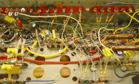
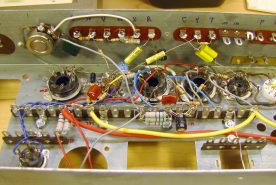
I began by removing the two wiring boards holding many of the resistors and capacitors, cutting the leads close to the board to leave the wires as long as possible for possible re-use. I then proceeded to unsolder all components and wires remaining in the chassis, except the filament heater wires and the wiring between the tubes and transformers in the percussion section.
Although I was careful during the unsoldering process, using a solder sucking tool and fine picks and pliers to unwrap each wire or component lead, I did manage to break a solder terminal off two tube sockets. I ordered replacement sockets when I placed my order for the resistors and capacitors needed for the rebuild.
Designing a New Layout
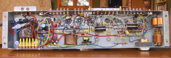
Instead of reusing the two eyelet boards that held many of the resistors and capacitors, I decided I wanted to use terminal strips instead. This has the advantage of keeping the layout fairly two-dimensional, making it easier to see and work on. It would probably not have been feasible to build the amplifier this way originally, as many parts were much larger than they are today, so the space afforded by the extra dimension was needed to make it all fit.
Having done a lot of point to point wiring in my teenage years, I knew there would be a lot of “soldering myself into a corner”, requiring parts to be unsoldered and moved around. This generally resulted in a mess, and a few damaged components and terminals along way. Instead I decided to apply the discipline required when making and using a printed circuit board, and designed the entire layout, at actual size, on paper first. To save time, I created a blank layout sheet with all the terminal strips and tube sockets in place using Photoshop, and then printed copies as needed.
To aid in drawing consistently sized components, I made a template from thin plastic sheet, with cutouts for ½W, 1W, and 2W resistors, and various sizes of capacitors. The drawing itself was done in pencil, since mistakes and bad ideas were inevitable.
I worked on the layout one sub-section of the amplifier at a time, working from an enlarged print-out of the schematic showing one sub-section per page. As I added each component and connection to the wiring diagram, I highlighted the corresponding parts of the schematic. Once the layout was completed, I scanned it and printed out another copy, and compared it carefully with the schematic, highlighting corresponding connections on both. This caught a few errors, which I corrected on my original working copy.
Once I was happy with the layout, I drilled holes in the chassis for the terminal strips, and fastened them using 6-32 bolts, nuts, and lock washers.
Obtaining Parts
The vast majority of the resistors in the original amplifier were rated at ½W, although a handful were larger. Virtually all the capacitors were rated 400V or more. Working from both the schematic and the original amplifier, I determined the appropriate rating for each part. I ordered these parts from TubeDepot.com. I chose modern carbon-film resistors instead of new-old-stock carbon composition resistors, as the newer resistors would never change in value or become noisy.
Some values of resistor were simply not available. For example, R101 is specified as a 180Ω 6W resistor. Instead, I used a parallel combination of two 560Ω and one 510Ω 2W resistors. In other cases, I was able to improve upon Hammond’s choices, such as replacing the parallel combination of 22kΩ 1W resistors R14 and R15 with a single 11kΩ 2W resistor.
The following table lists all the part substitutions made:
| Designator | Hammond Part | Replacement Part | Comments |
|---|---|---|---|
| C5, C31 | 330nF 150V | 3 × 100nF 600V parallel | had many on hand |
| C9, C56 | 20nF | 2 × 10nF 600V parallel | had many on hand |
| C24, C25, C28 | 47nF | 10nF and 39nF 600V parallel | had many on hand |
| C30, C64 | 25μF 25V | 33μF 25V | had on hand |
| C63, C66 | 20μF 400V | 22μF 500V | |
| C65 | 40μF 400V | 47μF 500V | |
| R14 ∥ R15 | 22kΩ 1W each | 11kΩ 2W | |
| R79 ∥ R80 | 10Ω ½W each | 5Ω 1W | |
| R92 | 500Ω 3W | 2 × 1kΩ 2W | |
| R93 | 30Ω 3W | reused from donor amp | wirewound |
| R95 | 3kΩ 6W | reused from donor amp | wirewound |
| R96 | 6kΩ 10W | reused from donor amp | wirewound |
| R98 ∥ R99 | 2.2kΩ 1W each | 1.1kΩ 2W |
The Rebuilding Process
With the chassis prepared, and all new resistors and capacitors received, it was time to set to work installing components. This was my first vacuum tube project, so it was a bit of a learning process.
Just like my section-at-a-time design of the layout, I installed and soldered parts and wires one section at a time. Components were installed by threading the leads through the appropriate terminals, wrapping them half way around for a secure mechanical connection. Once all the leads going to a terminal were in place, they were soldered. I used the same 45W iron I use for all my electronic projects, but with a much wider tip than usual.
As each part was installed, it was marked with a highlighter on a copy of the wiring diagram.
The astute reader may notice that a few parts (most notably, the large capacitors) are missing from the wiring diagram. These were installed towards the end of the construction, partially obscuring other parts, so they were left off the diagram for clarity.
After all the components except for the power and output transformers were in place, I checked all the connections to ensure they were properly soldered. I then printed out a fresh copy of the sectioned schematic, and checked every component and connection in the amplifier directly against the schematic, bypassing the wiring diagram. This would detect both wiring errors, and any errors that were missed during the earlier check of the wiring diagram.
Adding Fuses
The original design of the AO-29 by Hammond does not contain any safety fuses. In the event of certain failures, such as a shorted power supply capacitor or a plate-to-ground short in the rectifier tube, this could result in catastrophic damage, and possibly even a fire.
After extensive reading of discussions about this issue on various on-line organ forums, as well as personal correspondence with Mike at TrekII.com (which sells a fuse retrofit kit for the Hammond AO-28), I designed a fusing scheme for the AO-29.
There are a total of seven fuses. One is in the hot lead of the primary side of the transformer (I use a polarized plug to ensure that the hot and neutral leads are always connected correctly). There are also fuses in both leads of each of the three transformer secondaries: 5V, 6V, and 320V.
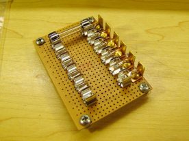
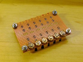
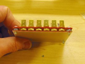
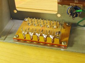
The primary fuse is implemented using an in-line fuse holder, much like those used for automotive applications. The secondary fuses are all contained in a fuse block, built from scratch using PC-mount fuse clips on stripboard.
- Top view of the fuse block, showing PC-mount fuse clips and spade connectors.
- Bottom view of the fuse block. Soldered brass bolts and nuts secure the spade lugs.
- A piece of 1.6mm fibre glass board insulates the fuse holder from the chassis.
- The fuse holder is fastened to the chassis with four 6-32 bolts and nuts.
Not shown in the last photo above are the wires from the fuse block to the amplifier circuitry. These were soldered to the board at the end closest to the top of the chassis (while the board was not installed) and then routed to the appropriate points in the circuit.
Final Assembly
With all the components and the fuse block in place and wired up, it was time to do a double transformer transplant. The power and output transformers were carefully removed from the existing amplifier, and installed and wired into the rebuilt one.
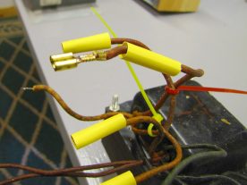
- The transformer secondary leads were terminated with heat shrink insulated female spade connectors.
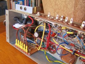
- The transformer has been installed and connected to the fuse block.
For ease of assembly, the secondary winding connections of the power transformer were terminated with female spade connectors, crimped and soldered. These were then insulated with heat shrinkable tubing, and connected to the fuse block after the transformer was bolted in place.
Testing and Reinstallation
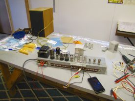
Before reinstalling the amplifier in the organ, I performed one final inspection, and then tested it on the bench. I made up a cable with a 4-connector TRRS plug for my Android phone on one end, and alligator clips on the other. I connected the ground and left channel leads to the amplifier’s ground and A inputs respectively. The output was connected to an 8Ω hi-fi speaker. I started some organ music playing on the phone, powered up the amplifier, and was pleased to hear it playing through the speaker. I then repeated the test using the B input. Testing of the pedal and percussion circuitry would have to wait until after installation.
- On the bench with a speaker connected to the output, and Klaus Wunderlich to the input.
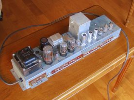
- The finished amplifier, ready for reinstallation in the organ.
After I was confident that everything was working correctly, I reinstalled the amplifier in the organ. I turned it on, waited for it to warm up, and was pleased to discover that everything was functioning! I did need to adjust the pedal cut-off and percussion potentiometers as described in the Hammond M-100 series service manual.
Replacing Other Resistors in the Organ
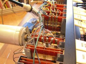
Although the sound quality was greatly improved, with much less noise than before, there was still the occasional rumbling sound. I came to the conclusion that I should replace the remaining resistors in the organ, most of which are installed on the various switches.
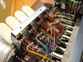
- Most of the resistors on the switches were readily accessible.
- Some switch blocks had to be unmounted to access parts on the bottom.
After all the resistors in the organ were replaced, the noisy gremlins were exorcised, and the organ sounded like new.
Results
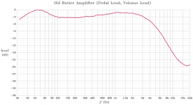
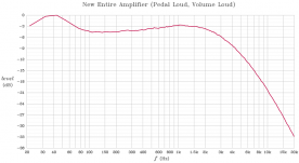
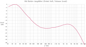
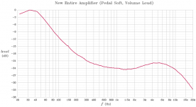
Before beginning this entire project, I made several recordings of the amplifier. I injected pre-recorded white noise into the A input of the amplifier, and recorded the output at the speaker terminals via a line-out connector I added in the past. I then used Audacity to perform a spectrum analysis of the recorded data, exported this as text, and generated the graphs below using a Maple program.
- Frequency response of the original amplifier with pedal at full volume, and Volume Soft switch off.
- Frequency response of the rebuilt amplifier with pedal at full volume, and Volume Soft switch off.
- Frequency response of the original amplifier with pedal at full volume, and Volume Soft switch on.
- Frequency response of the rebuilt amplifier with pedal at full volume, and Volume Soft switch on.
To compensate for the slightly non-flat frequency distribution of my white noise sample, I subtracted the spectrum of the input noise from each output recording, leaving only the effect of the amplifier.
I also measured the response of various sub-sections of the amplifier. Rather than reproducing all those here, I refer the reader to this thread on The Organ Forum: Hammond AO-29 Frequency Response.
Conclusion
Doing this rebuild has been on my to-do list for many years now, and I’ve been putting it off due to the work involved. It turned out to be a quite enjoyable project however, and although it was a lot of work, it didn’t feel like it at the time. The end result of a much quieter amplifier was well worth the effort.
Related Articles
If you've found this article useful, you may also be interested in:
- Hammond Organ Tonewheel Generator Capacitor Replacement and Calibration
- Overhauling the AO-29 Amplifier in the Hammond M-100 Series
- Window Seat Bookcase Tone Cabinets for a Hammond Organ
- Retronome – A Versatile Analog Drum Machine for My Hammond Organ
- Overhauling and Improving the Hammond M-100 Series Vibrato System
- Adding a Rotary Speaker to a Hammond M-111 Organ

If you've found this article useful, consider leaving a donation in Stefan's memory to help support stefanv.com
Disclaimer: Although every effort has been made to ensure accuracy and reliability, the information on this web page is presented without warranty of any kind, and Stefan Vorkoetter assumes no liability for direct or consequential damages caused by its use. It is up to you, the reader, to determine the suitability of, and assume responsibility for, the use of this information. Links to Amazon.com merchandise are provided in association with Amazon.com. Links to eBay searches are provided in association with the eBay partner network.
Copyright: All materials on this web site, including the text, images, and mark-up, are Copyright © 2025 by Stefan Vorkoetter unless otherwise noted. All rights reserved. Unauthorized duplication prohibited. You may link to this site or pages within it, but you may not link directly to images on this site, and you may not copy any material from this site to another web site or other publication without express written permission. You may make copies for your own personal use.


Edwin
February 03, 2017
Hi there,
Fantastic work! I’m in a similar situation myself and may well pursue the same path, although it’s tempting to keep the original eyelet boards for originality’s sake. They do make working on it tricky though…
As I also have a spare field coil AO-29, I’d love to know what other changes you had to make other than swapping the power and output transformers – the field coil load is swapped for R101 and the jumper removed etc, but did you make the other changes in the power stage? Just curious how close to the schematic you pursued it…
Stefan Vorkoetter
February 04, 2017
I did my rebuild by completely following the permanent magnet version schematics. I just happen to have a field coil version available to do the build in (rather than rebuild my existing permanent magnet version in-place). I only kept the intermediate transformers from the field coil chassis to minimize the number of parts I had to remove from the working amplifier to make it easy to go back if needed.
Edwin
February 08, 2017
Makes total sense – I’m effectively removing my permanent magnet chassis (as it’s sufficiently in need of repair to warrant a complete teardown) and I’m going to drop in a field coil chassis to use while I take time to rebuild the main chassis. I’ve been tempted to take the power and speaker transformers out of the permanent magnet chassis and make the few mods required to use those in the field coil chassis, but instead I think I’m going to use Hammond’s TSB #27 and fit a lossy 700ohm 20W resistor in place of the field coil, leaving the rest of the field coil chassis stock. Next up – I’ve a hare-brained scheme to calculate the gain and impedance values for each stage and replicate with a DIY solid-state design.
Stefan Vorkoetter
February 08, 2017
If the field-coil amp is only temporary until you get the PM one rebuilt, there’s probably not a lot of point modifying it beyond using the 700 Ohm resistor in place of the field coil. I had considered building a solid-state replacement too, but decided it was more trouble to design it than to just fix the old tube amp.
Andrew
March 05, 2017
Hi. What fuse values did you use?
Tim
March 06, 2017
Hey Stefan, could you list what ratings of fuses you used in which line?
Thanks
Stefan Vorkoetter
March 07, 2017
I used 250mA on the 320V leads, 4A on the 5V, and 5A on the 6.3V if I remember correctly. The fuse on the primary side is 1.5A.
Tim
March 07, 2017
Thank you for your reply, are they all slow blow?
Stefan Vorkoetter
March 08, 2017
Well, I didn’t specifically select slow-blow fuses, but looking at the spec sheets for them, they all say, “Response Time: Slow”, so I guess they are.
Tim
March 10, 2017
I have made a list of every component on the schematics for my M100, I am struggling to identify the required voltages for the capacitors, particularly the ceramic “disk” type, did you make any notes or have any tips? Sadly I can’t really work from the amplifier parts as it has been really messed with.
Thank you in advance.
Stefan Vorkoetter
March 10, 2017
Ceramic disk type capacitors are readily available in very high voltages, so if you go with anything 450V or higher, you’ll have no problems. I used mostly 600V caps since I had those on hand.
Flip
August 29, 2017
Terrific job, and way beyond my current abilities, I’m afraid! I have a ’66 M111, love it, but I’m trying to repair it right now. Thanks for the inspiration, Stefan.
Steve G
August 16, 2019
Hello Mr Vorkoettr
I will try to make this short . I got a M 100 with a AO-29 from a guy for 50 bucks it was seized up both the TW Gen. and Run Motor both are freed it up now and starts up easy now but I have NO Audio from the key boards .I put in a new start Res. and a new start and Run switch from Tonewheel Hospital and a new power cord.The peddles make a faint sound .I have the same amp you have in your photos above .I also took off the swell cover and cut the RCA hot CAP wire moved it back and taped it .then took the yellow wire and soderd a 1UF resistor to it and the other end to the center post of the RCA. I did this from Mods that I seen. ( I PUT IT BACK TO STOCK) and still no audio sound. Please if you have time in the simplest language possible give me some direction /photos ,videos ,anything at all .I dont want it to sit any longer I did all I know and don’t read syhmatics .Thank you for your time I hope this makes sense. Steve Acton Ca.
Stefan Vorkoetter
August 16, 2019
In the simplest language possible? “Call an organ tech.”
The only way you’re going to figure this out is by tracing the problem from the tone generator, through the keyboards, drawbars, matching transformer, and finally amplifier. That will require reading the schematics.
scjeremias
October 24, 2019
I am looking at a choke from a Hammond Organ Tube Amplifier (choke #AO-16682-3); it is 18H ~280ohms DCR. Do you have any idea how much current it will handle?
Thanks in advance.
Stefan Vorkoetter
October 24, 2019
Sorry, I don’t. There are no chokes in the AO-29 amplifier, and that’s the only one I have any experience with. Do you have a schematic showing where this choke is used? It should be possible to determine the required current rating from that.
Tom McCann
October 03, 2020
I just did a rebuild/refresh on an M3 amp for a field coil speaker. I rigged up a bench test as you did, and. I am pleased to report I get amplified music! But I also get a lot of 60 Hz hum. I am assuming it is because there are a lot of open connections and my input cables are long and unshielded. Do you remember if you got a lot of hum during your bench test?
Stefan Vorkoetter
October 04, 2020
I used shield cables in my bench test, but it’s very likely that the lack of unshielded cables is picking up the hum.
Bill Plack
January 25, 2021
Hey Stefan! A quick question about an AO-29 that I’m going to be working on, it’s in a beautiful M-3 that I just rescued. I want to replace the beat-up power cord with a new 3-prong cord – it looks fairly straight-forward, but I’m not a true amp tech by any means. I love and collect old tube amps, and I know a little about them – I know how to drain the caps, I can solder, and I’ve done some work – I’ve replaced the power cords on my two Bassman amps, etc. On them, I added a lug to the green ground wire, and attached it to a bolt mounting the power transformer to the chassis. In doing research, I’ve heard mixed messages about doing that on this AO-29 – some have mentioned a ‘ground loop’ that won’t play well with a 3-prong cord, others say just mount it the green to the chassis. I’m using a new power cord with black, white and green – I’d assume (I know what they say about assumptions!) black to black, grey to white, green to ground. I have to do some unsoldering to pull the chassis, once I do that, I’ll be checking over the electrolytics and such. But in the meantime I’d just like to make it safe to fire up (I’ve already had it running, but that frayed power cord makes me nervous). Thanks in advance for any info that you can share, I’ll be happy to buy you a few cups of coffee!
Stefan Vorkoetter
February 10, 2021
Hi Bill … Even after doing all the work on my Hammond, I’ve never switched to a ground plug. However, I did replace the regular wall outlet that it is plugged into with a ground-fault outlet instead. Such an outlet doesn’t actually check the ground itself, but rather that there’s a difference in current flow between one pin on the plug and the other. If that happens, it indicating some current must be flowing elsewhere, like the person playing the organ, and will immediately cut off the power flowing to the Hammond. Note that I’ve noticed that it never does this with the cable plugged in one way around, and occasionally when plugged in the other way (it’s the old style plug that can go in either way).
Red Acheson
December 02, 2022
Hello all 🙂
I just acquired a Hammond M3 and its missing the 3 furthermost tubes…V7 8 AND 9
Im trying to figure out what tubes go in these positions and also, If I can run the organ without them?
About to buy some tone oil, should be ready to test in a week or so.
Thanks!
-Red