The Battery Eliminator Circuit
December 1, 2003 for QuietFlyer Magazine
The Battery Eliminator Circuit, or BEC, is one of the tools at our disposal to reduce weight in our electric models. A typical four-cell 600mAh nickel cadmium (NiCd) battery supplied with most radio systems weighs about 3.3 oz (94 g), a significant fraction of the weight of a typical beginner’s electric model (such as a Great Planes ElectriCub or Spectra). Lighter batteries are available, but with the trend towards even smaller and lighter models, even a 1.5 to 2 oz (43 to 57 g) battery is too much to carry. The model will still fly, but it’s flight characteristics will be compromised.
The BEC lets us eliminate the receiver battery, using the motor battery to provide power to the radio system instead. This has some ramifications as to where and how we can use a BEC, and of course, it also means we can’t use BEC in a glow powered model, or a pure sailplane.
How it Works
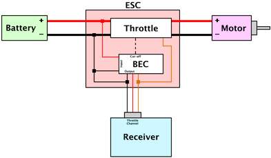
Typically, the BEC is part of electronic speed control (ESC) which acts as the motor’s throttle. Conceptually, it is completely separate from the part of the ESC which controls the motor speed, although the two parts do interact somewhat, and share some of the same wiring. Figure 1 shows the components of a typical power system, and how it relates to the internal arrangement of a BEC-equipped ESC.
The BEC supplies power to the receiver through the same lead from which it gets the throttle signal. Each channel connector on the receiver has a plus, minus, and signalpin. Power can be supplied via the plus and minus pins of any channel; it is not necessary to connect to the receiver’s "Batt" connector (many small receivers intended for use in BEC equipped models don’t even have a "Batt" connector).
Notice that both the throttle and the BEC components of the ESC are connected to the power wires coming from the battery. Furthermore, both perform very similar functions, but do so in very different ways.
The throttle controls how much power reaches the motor, and it does this by turning the power to the motor on and off at a high rate of speed (about 1,500 to 3,000 times per second in most modern ESCs, or 50 times per second in the now obsolete frame-rate ESCs). The amount of power that the motor sees depends on the fraction of the time that the power is on. At full throttle, it is on all the time. At a partial throttle setting, it is on part of the time.
The BEC on the other hand controls how much power reaches the receiver and servos. Unlike the throttle, whose purpose is to vary the effective voltage reaching the motor, the BEC must maintain a fixed voltage with which to supply the radio system, and it must do so under varying motor battery voltage and servo loads. Furthermore, the power supplied to the receiver must be "clean". There can be no electrical noise or voltage fluctuations. That is a tall order considering that the power source (the battery) is also supplying the electrically-noisy motor.
Voltage, Current, Resistance, and Power
A common theme in this column is the relationship between voltage, current, and power. This is because almost everything in electric flight depends on this relationship. Recall that power is equal to current times voltage, or P = I x V. Another important relationship is Ohm’s law, which states that voltage equals current times resistance, or V = I x R.
The BEC’s job is to reduce the voltage of the motor battery (typically 7 to 12 Volts) to that required by the radio system (5 Volts), while meeting the varying current requirements of the receiver and servos. A simplified BEC circuit is shown in Figure 2. Assuming that the radio and servos are drawing a fixed amount of current, we can calculate a setting for the variable resistor so that the receiver sees 5 Volts. For example, if the battery voltage were 9.6 Volts, and the receiver and servos were drawing 0.2 Amps of current continuously, we could plug the voltage difference (9.6 – 5) and the current (0.2) into Ohms law, giving 4.6 = 0.2 x R. We can solve this for R, which gives 23 Ohms.

Figure 2. If the battery voltage and radio system current remained constant, a simple resistor would suffice as a BEC.
This simple circuit has two drawbacks. One is that a particular resistance is only correct if both the current draw and the battery voltage remain constant. The other problem is that the current multiplied by the voltage difference represents power lost in the resistor in the form of heat (P = I x V).
The first problem is easily circumvented by using a device called a linear voltage regulator, which basically functions as a resistance that changes its value as the battery voltage or current demand changes, keeping the output voltage at a constant 5 Volts. A few additional components (capacitors) filter out electrical noise on both the input and output side of the regulator.
The more serious problem is heat. In our example, the power to be dissipated as heat is 0.2 Amps times 4.6 Volts, or 0.92 Watts. We will need a 1 Watt resistor, and it will get quite warm. However, suppose that the current goes up to 0.4 Amps for a while (for example, while pulling out of a dive, the elevator servo will be working very hard, and require more current). This will require a different resistance to maintain 5 Volts, but that has already been taken care of by using a voltage regulator instead. The heat power loss is now 0.4 x 4.6, or 1.84 Watts. That is a significant amount of heat for a tiny voltage regulator to get rid of, and it will get quite warm trying to do so.
It is this need to dissipate the voltage difference, multiplied by the current demand, as heat, that causes ESC manufacturers to put restrictions on BEC use. These restrictions specify the maximum number of cells (i.e. maximum battery voltage) and the maximum number of servos (i.e. maximum current demand) that can be used with the BEC.
A Better Way?
The astute reader may have wondered how the throttle is capable of providing reduced power to the motor at much higher currents than the BEC provides power to the radio, yet not suffer from overheating problems. The answer lies in the on/off switching that the throttle performs.
Rather than providing a lower voltage for reduced throttle operation, the throttle simply switches the full voltage on and off at a high rate. This way, the throttle is either conducting full current with no voltage difference between the battery and motor (so I x V equals zero), or no current at all (so I x V is still zero). Hence, no power is dissipated as heat within the throttle (in reality, some power is still lost because the throttle does not have zero resistance).
It is theoretically possible to do something similar for a BEC voltage regulator, using a circuit called a switching regulator. However, such circuits are relatively large, heavy, and expensive. It is also difficult to design a switching regulator that can produce clean enough power to reliably operate the radio receiver. A linear regulator is much cheaper, and sufficient for most applications.
BEC Ratings
Now that we know that a BEC is limited by its ability to shed heat, and that the amount of heat generated is equal to the product of the current, and the input-output voltage difference, we can see why most manufacturers rate their ESCs with BEC as to the maximum number of cells and/or servos that can be used.
The more cells there are in the battery, the higher the BEC input voltage, and hence the higher the voltage difference between the input and the 5 Volt output. And, the more servos being used, the higher the average current draw.
A typical ESC with BEC might be rated as follows:
| NiMH Cells | Standard Micro Servos | High Torque Servos |
|---|---|---|
| 5 to 6 | 4 | 4 |
| 7 to 8 | 4 | 3 |
| 9 to 10 | 3 | 2 |
| 11 to 16 | No BEC | No BEC |
Notice that as the number of cells increases, the number of servos permitted decreases. That way, as the voltage difference goes up, the expected current draw goes down. Beyond 11 cells (for this example), the BEC cannot be used at all because the voltage difference is too high to safely supply any significant amount of current.
In any model, but especially in a BEC equipped one, it is important to ensure that all control surfaces move freely. If a control surface or pushrod sticks or binds, the servos have to work harder, and they will draw much more current. This can cause the BEC’s regulator to overheat and shut down, resulting in loss of radio control. A sure sign of such a problem is a servo that hums or chatters when a control stick is held at full deflection.
Motor Cut-off
In a typical electric flight, the motor battery is dead or nearly dead by the end of the flight. This is very undesirable if the motor battery is also supplying power to the receiver and servos, since you would no longer be able to control the model.
For this reason, all BEC-equipped model aircraft ESCs have a motor cut-off feature which turns off power to the motor when the battery is running low, leaving enough power to operate the radio system for some time. This means that the BEC must be able to "tell" the throttle to turn off the motor, which is represented by the dotted line in Figure 1.
Because the receiver and servos take far less power than the motor, cutting off the power even 10 seconds before the battery is dead will reserve many minutes of radio system power. The problem is knowing when the battery is almost dead.
Some of the programmable digital ESCs (such as those by Castle Creations) offer a user selectable cut-off voltage. Some older analog ESCs (such as the ones produced by Lofty Pursuits, or the one whose construction I described in the July 1999 issue of Sailplane & Electric Modeler) have adjustable cut-off voltages (Lofty Pursuits’ by a user-installed resistor, mine by a small potentiometer).
In order to know what to set the cut-off voltage to, you need to know what the battery voltage will be with the motor running when there are only a few seconds of power left. This is best determined by running the motor at full throttle on the ground, monitoring the voltage, and noting what it was a 10 or 15 seconds before the power drop-off at the end.
Many inexpensive speed controls have a fixed cut-off voltage that was chosen to work with the minimum number of cells the speed control is rated for. Usually this is 5.5 Volts, for use with a 6-cell battery (5.5 Volts is also the lowest input voltage at which the regulator can produce a 5 Volt output). Unfortunately, this cut-off voltage is too low when operating with 7 or more cells. For example, a 10-cell battery at 5.5 Volt very likely has only a few seconds of radio system power left in it.
Ironically, this is less of a problem with an inexpensive battery than with a costly pack of matched cells. In the inexpensive battery, the voltage will drop this low when a few of the cells are completely dead, and the remainder still have some useful charge left. In a matched pack, the voltage will only drop this low when all the cells become almost depleted, all at the same time.
Some ESCs, like the one on my website (www.stefanv.com/rcstuff/escbec.htm) don’t have a sudden cut-off at all. Instead, as the battery voltage drops, the ESC automatically reduces the throttle to take some of the load off the battery, keeping the voltage above the cut-off level. The reduction in power makes the pilot aware that time is running out and that it’s time to land.
Lithium Considerations
Lithium-Ion and Lithium-Polymer batteries have the special requirement that they not be discharged too low (3 Volts per cell under load). You must use an ESC that will cut-off the power before that level is reached, or cell damage will occur.
Restart
Most digital ESCs have an after-cut-off restart feature, which is usually activated by moving the throttle stick to off after the motor stops, and then applying partial throttle again. This can give you an extra bit of power to stretch that final approach and make the runway. Do not be tempted to eke a few extra seconds of flying out of this feature, or you risk depleting the battery too far to keep the radio system working.
Electric Sailplanes
In general, it is not advisable to use a BEC in a sailplane. The motor cut-off in a BEC-equipped ESC is intended to provide a few minutes of radio power in order to land the plane, whereas a sailplane can be expected to stay airborne for many minutes, or even hours, after motor shutdown. If you do use a BEC, never run the motor for so long that the BEC shuts it off. It’s probably best not to use more than two-thirds of the motor battery’s capacity, ensuring that you have plenty of radio power left for a long silent flight.
Related Articles
If you've found this article useful, you may also be interested in:
- What About the Wires?
- On Fuses in Electric Flight
- Electric Flight Wiring
- NiCd and NiMH Battery Care
- To BEC or Not To BEC
- Electric Flight Power Connectors
- Using Sanyo 1100AAU Cells for Speed 400
- An Electronic Speed Control Primer

If you've found this article useful, consider leaving a donation in Stefan's memory to help support stefanv.com
Disclaimer: Although every effort has been made to ensure accuracy and reliability, the information on this web page is presented without warranty of any kind, and Stefan Vorkoetter assumes no liability for direct or consequential damages caused by its use. It is up to you, the reader, to determine the suitability of, and assume responsibility for, the use of this information. Links to Amazon.com merchandise are provided in association with Amazon.com. Links to eBay searches are provided in association with the eBay partner network.
Copyright: All materials on this web site, including the text, images, and mark-up, are Copyright © 2025 by Stefan Vorkoetter unless otherwise noted. All rights reserved. Unauthorized duplication prohibited. You may link to this site or pages within it, but you may not link directly to images on this site, and you may not copy any material from this site to another web site or other publication without express written permission. You may make copies for your own personal use.


Alan Littlewood
October 16, 2007
A very well written and thorough treatise on the topic.
Hooya
November 22, 2007
Most everything in my life has come naturally from first principles: Understand the theory; own it. Make it mine. Then go out and start doing it. First, make the more obvious mistakes. Then — if I’m any good at it — stretch to make some of the more difficult, complex or interesting mistakes. Occasionally, after I’ve been tinkering with something for a long time – maybe put it away and then come back to it after months, or even years – occasionally I’ll make a NEW mistake that nobody’s ever made quite that way before. And thats when I know I’m starting to get pretty good… Anyway, life’s been kinda crazy these past years and haven’t really had any "extra" time to speak of. Jumped right into RC helis w/o reading or knowing a lick cause I figured if I saw how much there was to learn I’d just turn around and walk back out the door, if I had any sense. But flyin’s cool, and I like to keep doing it. So I came across your primer and it gave me Exactly what I
Dhrubajyoti Biswas
December 06, 2010
Gud Post!!
Graham
March 17, 2011
Thanks
I have an old Futaba receiver that is BEC but was unsure whether it supplied power? or it would work with an ESC with
BEC noiw all is clear although are there other servo type devises that have BEC or is it exclusive to the speed controller?
Regards Graham
Stefan Vorkoetter
March 19, 2011
Graham, BEC is provided by the receiver (or sometimes a stand-alone device that takes the place of the battery). The BEC then provides power to the receiver, servo, and ESC.
george
April 21, 2012
can i use batteries instead of BEC with a 60amp ESA to run a 750kv motor??
sai
October 25, 2014
Sir, I am inspired about your work on electronic speed controllers. Please provide us detailed information on building a 40 to 50 amp operable at 11.1 volt brushless motor ESC for my aircraft model