Build an On/Off Motor Controller with Brake
May 28, 2006
Modern electronic speed controllers (ESCs) are very efficient, but they still have some drawbacks. An inexpensive ESC with two IRFZ40 MOSFETs has an on-resistance of 14 milliOhm. At 20A current, this means a voltage drop of 0.28V, and a power loss of 5.6W. Furthermore, to build an ESC with a brake generally requires an expensive P-channel MOSFET.
A relay-based on/off controller on the other hand can be very efficient. A typical relay has a contact resistance of 3 milliOhm. At 20A, this translates to a voltage drop of 0.06 volts, with a power loss of 1.2W. The relay itself typically consumes around 0.4W. And, by using a double throw relay, one gets a brake for free.
There are two main problems with a relay-based on/off controller. One is that there is no control over motor speed; it’s either off or it’s at full throttle. Such a controller is best suited to electric gliders, which for their size, typically have relatively small motor systems, and therefore need full power to climb.
The other problem is finding a suitable relay. It took me a long time to find one, and after I finally found one at Maplin’s (while visiting the U.K.), I discovered that there is one right under my nose at Radio Shack. What prevented me from finding it was the incorrect description of the relay in the catalogue and on the packaging. It turns out that part #275-249, which was advertised and packaged as a 1A relay, is really a 5A relay, and each of the parallel sets of contacts within the relay is rated at 5A. The pinout given on the back of the package was also incorrect. Radio Shack has since corrected both the catalogue and the packaging.
Now, you might be wondering why one would use a 10A relay to switch 20A. Well, it will work, at the expense of reduced life of the relay. But, the relay is easy to get and inexpensive. Another thing you may be wondering is how to switch a 12V relay with a 7-cell pack. It turns out that this too will work just fine. The relay does not require 12V. It will work well at 8.4V, and once on, will stay on at even lower voltages.
Specifications
This controller has the following specifications:
- Size: 1.5"L x 1.3"W x 1"H.
- Weight: approximately 1oz.
- Current: 10A nominal, 20A maximum recommended.
- Voltage: 7.2V to 12V (6 to 10 cells).
- No power-on glitch.
- Throttle stays off when transmitter is off.
The Circuit
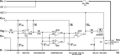
The circuit for the controller begins with a buffer, consisting of R1, R2, R3, and Z1A, which isolates the receiver from the rest of the circuit and makes operation of the circuit independent of the exact signal levels from the receiver.
R4, R5, and C1 form an integrator. Whenever a pulse comes in, Z1A inverts it, and discharges C1 through R5. In the space between pulses, C1 recharges through R4 and R5. The longer the pulse, the lower C1 will discharge.
The comparator stage, consisting of Z1B and Z1C wired in parallel (to provide a larger current sink for C2) detects if C1 ever drops below a threshold (set by R2 and R3). If it does, C2 is quickly discharged during the time that C1 is below the threshold. Between these discharge times, C2 is slowly charged through R6. C2, R6, and Z1D form a missing pulse detector. As long as C1 periodically goes below the threshold, C2 will be discharged and also remain below the threshold, thereby keeping the output of Z1D low. If C1 stops going below the threshold (because the pulses have become shorter), C2 will recharge, and Z1D will go high.
The final stage, consisting of R7, R8, and Q1 turns on the relay whenever the output of Z1D is low. So, short pulses from the receiver will leave the relay turned off, and long pulses will keep it turned on.
The arming switch is wired between the motor battery positive side and Q1. When the switch is open, no current can flow through Q1, and consequently, the relay cannot be turned on.
Construction
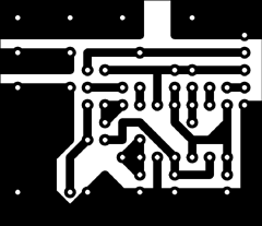
The circuit is best built on a printed circuit board. It’s not hard, and I describe the process in detail in the article, Making Excellent Printed Circuit Boards.
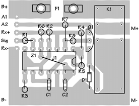
There are a few unusual things about the construction. The two holes on either side of the space marked F1 should be drilled to tightly fit the shaft of uninsulated female spade connectors. After inserting these and soldering, the rest of the shaft (on the solder side) can be sawed off with a razor saw. These two connectors make up the fuse holder.
Follow the Component Side diagram for parts placement:
The common lead of R7 and R8 go into the same hole on the board. This will require that you drill that hole slightly oversize. Likewise, the relay pins will probably require slightly oversize holes.
Jumper J1 must be installed before chip Z1.
You should use a socket for Z1. An IC is easily damaged by soldering, and extremely difficult to remove without damaging the board. Using a socket can save a great deal of trouble.
The two semiconductors, Q1 and D1 should be installed last, since these are also easily damaged by soldering and they could overheat while soldering other components to the same traces. The body of transistor Q1 will most likely need to remain about half an inch above the board, since it won’t fit between R4 and the relay. Be sure to install Q1 and D1 the right way around.
The arming switch can be any sort of on/off (not momentary) switch that you desire. Simply connect its contacts by wire to the pads marked A1 and A2. In this circuit, the arming switch controls power to the relay, not power to the motor, so a heavy duty switch is not needed.
Connect an appropriate servo lead to the R+ (red), Sig (white, orange, or yellow), and R- (black or brown) pads. There may be some old equipment that uses different colour schemes, so double check.
Tin all the high-current carrying traces (or better yet, solder some desoldering braid to them). Solder 12 or 14 gauge wire to the B+, B-, M+, and M- locations. There should be about ½" of wire length making contact with the board in each location to assure low losses.
Testing
Double check your work, making sure there are no solder bridges, and that you didn’t make a mistake copying the circuit board layout. Check that all the components are in place, but do not insert Z1 into its socket yet. Insert a 5A fuse (for testing) into the fuse holder.
Connect a motor battery to the B+ and B- leads, and use a volt meter to ensure that there are no high voltages on the servo leads (you don’t want to fry your receiver because of a wiring error).
Disconnect the power, insert Z1 into its socket, plug the servo lead into the appropriate receiver channel, connect the motor battery, and apply power to the receiver. Turn on the arming switch. Moving the throttle stick back and forth should make the relay turn on and off. It should switch approximately in the middle of the stick travel. Connect a 12V automotive lamp to the M+ and M- leads, and ensure that the lamp switches on and off. It should be on with the throttle stick forward. With the lamp on, turn off the arming switch and confirm that the lamp turns off.
Turn everything off, disconnect the motor battery, and hook up a motor (with a propellor). Replace the fuse with a 20A or 25A one. Make sure the motor is firmly fastened to something and that the propellor can swing freely. Turn everything back on in the following order: throttle stick to off, transmitter on, receiver on, arming switch on. Stay out of the plane of the propellor, and move the throttle stick to full. After a few seconds, move the throttle stick back to off. The propellor should stop almost immediately.
Installation
Installation is straightforward. Hook up everything as you did while testing. Install the arming switch in an appropriate place (I prefer the left side of the fuselage, just ahead of the leading edge of the wing, with forwards being ON). Make sure that the bottom of the circuit does not touch anything metallic. To prevent corrosion, I sprayed the bottom of the board with clear lacquer. Keep the motor and battery leads as short as possible. Also make sure your motor is equipped with suppression capacitors (I use three 0.1µF capacitors, one across the motor terminals, and one between each terminal and the motor case).
Due to the sudden starting and stopping of the motor when using a relay, it is not advisable to use such a controller with a gear box, as too much stress will be applied to the gears. A speed controller is a better choice for such a situation (or a soft-start controller, which costs just as much).
Before flying with this controller, do a range check. With the motor off, you should get the same range as without the controller (for most radios, this is 100ft with the antenna down; check your manufacturer’s recommendations). With the motor on, you should get at least 85% of the range you got with the motor off. If you do not pass this range check, do not fly!
Parts List
The following table lists all the parts needed, along with Radio Shack part numbers for those of you who don’t live near a decent electronic parts warehouse or surplus store. With some of the Radio Shack part numbers, you’ll end up with (and pay for) enough for five or ten controllers.
| Part | Description | Radio Shack |
|---|---|---|
| R1 | 4.7kΩ ¼W | 271-1330 |
| R2 | 3.3kΩ ¼W | 271-1328 |
| R3 | 2.2kΩ ¼W | 271-1325 |
| R4, R8 | 1kΩ ¼W | 271-1321 |
| R5 | 15kΩ ¼W | * |
| R6 | 1MΩ ¼W | 271-1356 |
| R7 | 10kΩ ¼W | 271-1335 |
| C1, C2 | 0.1µF 50V | 272-109 |
| D1 | 1N4148 or 1N914 | 276-1122 |
| Q1 | 2N3906, MPS2907, or equiv. | 276-1604 |
| Z1 | LM339 quad comparator | 276-1712 |
| K1 | 12VDC 5A DPDT relay | 275-249 |
| F1 | 14ga female spade conn. | 64-3039 |
* Use a 10kΩ and a 4.7kΩ wired in series if you can’t obtain a 15kΩ anywhere.
Addendum
Several of you have built this controller, and two people have reported a problem wherein the controller would refuse to shut off during a flight. After some head scratching and various e-mails back and forth, one of my correspondents determined that the current flowing through the trace from B- to M- was heating up C1 (and C2), which was causing the off-point to creep downwards until it was below the minimum possible throttle setting. One way to fix this problem is to use a physically much larger capacitor for C1, so it is less affected by the heat. The preferred way to fix it is to use a continuous length of wire for B- and M-, soldering the wire to the board along its whole length. That way, the circuit board trace doesn’t have to carry the full motor current, and will thus not overheat. Likewise, the B+ wire should reach all the way to the fuse holder, and the M+ wire should cover the full length of the M+ trace on the board. The trace between the fuse holder and K1 could also be reinforced with a short piece of wire or desoldering braid.
Related Articles
If you've found this article useful, you may also be interested in:
- BattMan II: Computer Controlled Battery Manager
- LED Bargraph Optical Tachometer
- High Speed NiCd Charger for Electric R/C
- Analog Bar Graph Expanded Scale Voltmeter
- Versatile Miniature High-Rate ESC with BEC and Brake
- Miniature High-Rate Speed Control with Battery Eliminator Circuit (BEC)
- Miniature High-Rate Speed Control with Brake
- Getting the Most from Your Radio Control System
- Low Cost Thermal Peak Detection NiCd Charger

If you've found this article useful, consider leaving a donation in Stefan's memory to help support stefanv.com
Disclaimer: Although every effort has been made to ensure accuracy and reliability, the information on this web page is presented without warranty of any kind, and Stefan Vorkoetter assumes no liability for direct or consequential damages caused by its use. It is up to you, the reader, to determine the suitability of, and assume responsibility for, the use of this information. Links to Amazon.com merchandise are provided in association with Amazon.com. Links to eBay searches are provided in association with the eBay partner network.
Copyright: All materials on this web site, including the text, images, and mark-up, are Copyright © 2026 by Stefan Vorkoetter unless otherwise noted. All rights reserved. Unauthorized duplication prohibited. You may link to this site or pages within it, but you may not link directly to images on this site, and you may not copy any material from this site to another web site or other publication without express written permission. You may make copies for your own personal use.


Jamie
January 22, 2009
I constructed a slight variation of this circuit using surface mount components, I omitted the relay as it is being used to control nav lights and the LED current is well within the capabilities of the transistors used. Works really well, adds a little wow factor turning on and off accessories at will.
Jamie
Saad Imtiaz
October 13, 2010
Have any one give me the idea about Remote control car’s circuit????
I urgently need … please
Alexandru Patrascu
May 05, 2011
again electronics… 😀
joribo
May 23, 2013
Detail addition:
When the relay drops off, the motor is short-circuited for braking. In case of a gear or folding prop this happens too abruptly, also the relay contacts wear down due to the current peak. So I put a resistor wire of 0.4 to 1 Ohm between the NC contact and ground to dampen the brake function. There is space on the underside of the PC board.
I have made both switch, and the speed controller with brake, and they work very well on Speed 400 and 500 motors.