Build a High Speed NiCd Charger for Electric R/C
February 10, 2002
A few years back, I published a design for a Low Cost Thermal Peak Detection Charger. Since then, I’ve designed several other chargers, in my ongoing quest to avoid having to spend money. Of course, in building all these designs, I’ve probably spent more than a really good commercial charger would have cost me. But designing and building is half the fun.
Since the early days of electric flight, we’ve been using chargers operating at about 4 or 5 Amps. Back when the most commonly used NiCd cell was the Sanyo 1200SCR, that produced full charges in 17 to 20 minutes. Nowadays (I’m writing this in February of 2002), the RC2400 is the NiCd cell of choice, yet most chargers still operate at only 5 Amps or so. At this rate, a full charge takes about 35 minutes.
An RC2400 cell can easily accept a charge rate of 10 Amps or even more, but even the slightest error in terminating the charge when the cells are full will result in cell destruction. Although the cell capacity has doubled, the size, and hence the ability to dissipate excess charge as heat, has remained the same. Thus, normal peak detection charging at such high rates is somewhat risky. Even thermal peak detection can be risky, because the insides of the cells may have reached much higher temperatures before the outsides get hot enough to terminate the charge.
The charger in this article gets around this problem by using a multi-stage charging technique, giving the benefits of a high charge rate without the risk of overcharging at that rate. It can safely charge a 7-cell RC2000 pack in about 14 minutes, and an RC2400 or CP2400SCR pack in about 17 minutes.
Theory
As a NiCd cell is being charged, two things happen which affect its temperature. Due to resistive losses within the cell, some of the charging current is converted to heat (I2R losses). At the same time, the chemical reaction that takes place during NiCd charging absorbs heat (i.e. it’s an endothermic reaction). If the charge rate is low, the cell will actually get cooler as it charges. If the charge rate is just right, the rate of heat absorption by the reaction will exactly match the rate of heat generation due to losses, and the cell temperature will remain the same. If the charge rate is too high, the cell will get warmer during charging.
Once a cell is fully charged, the endothermic chemical reaction stops. This means that continued charging current, no matter how low, will cause the cell to heat up. Higher currents will heat the cell up faster. At 10 Amps for example, the cell will heat up four times as fast as it would at 5 Amps. The rise in temperature when a cell is fully charged can be used to detect that the charge is complete. However, this limits the charge current that can be used, since too high a charge current will cause the temperature to rise before charging is done.
By charging at a high current until the temperature reaches a certain point, and then switching to a lower current until the charge is complete, we can get around this limitation.
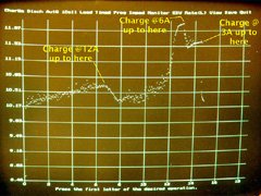
The charging starts off at a very high rate (about 12.5 Amps for an RC2400 pack), and stays at that rate for most of the charge. As the pack begins to warm up, the charging rate is reduced (to about 6.5 Amps). As the pack warms up further, the rate is reduced further (to about 3 Amps). Finally, once the pack reaches a temperature indicating a full charge, charging stops. The photo shows a typical voltage curve during a charge.
The Circuit
There are several parts to the charger, which are best looked at in isolation.
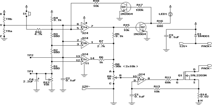
Diode D1 provides reverse polarity protection to the rest of the charger’s circuitry, since accidentally hooking it up backwards to the 12V source battery would damage Z1 otherwise. C3 acts as a power supply bypass capacitor.
Temperature Level Detector
TRa and TRb are a pair of thermistors configured as a voltage divider. TRa measures ambient temperature, and TRb measures the temperature of the pack being charged. Each thermistor’s resistance drops by about 4% for each 1°C rise in temperature. Therefore, as the pack temperature increases relative to its environment, TRb’s resistance relative to TRa’s decreases, and the voltage at their junction goes up.
This voltage is applied to the inverting (-) inputs of voltage comparators Z1a, Z1b, and Z1c. The non-inverting (+) inputs are connected to another voltage divider made up of R12, and R1 through R4. R12 is adjusted so that the voltages at pins 12, 3, and 5 of Z1 correspond to temperature increases of 6.7, 10, and 13°C respectively. As the pack temperature rises to 6.7°C above ambient, Z1c’s output will go low, followed by Z1b’s output at 10°C, and Z1a’s at 13°C above ambient.
C4 is there to ensure that the charger is initially off when first connected to the 12V source battery.
Charge Current Control
The outputs of Z1a, Z1b, and Z1c drive a resistive ladder network. The resistor values were chosen so that the voltage produced on the centre terminal of R9 will be proportional to the current levels desired for each temperature range. R9 controls the maximum current, and can be set appropriately by the user for the pack being charged.
Z1d, R11, R13, R14, C1, and Q1 roughly regulate the charging current based on the voltage from R9. Z1d measures the voltage across R14, comparing it to the voltage from R9. If the voltage across R14 is less than the voltage from R9, the output of Z1d goes high, causing the charging current to increase. If R14’s voltage is lower than R9’s, Z1d decreases the charging current. C1 slows down the response. As a result, the charging current actually oscillates around the desired value instead of being a steady current, which might be beneficial in breaking down crystalline formations within the NiCd cells.
Charge Termination
As long as Z1a remains high (i.e. charging is still in progress), Q2 remains switched on, which lights charge indicator LED1. It also keeps Q3 switched off. When the pack has reached 13°C above ambient, Z1a goes low, Q2 and LED1 turn off, Q3 turns on, and R18 reduces the voltage on pins 5, 3, and 12 of Z1. This prevents the charging from restarting as the pack cools off.
Starting the Charger
Start button S1 and resistor R10 do the opposite of Q3 and R18, pulling the voltage divider voltages up high enough to overcome R18 and thus start the charger.
Construction
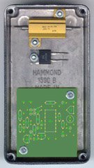
The circuit was designed to fit into a Hammond 1590B cast aluminum project case. This case was chosen because it was small, and the heavy aluminum would make an excellent heat sink for Q1 and R14. The lid of the case is drilled for R9, LED1, and S1. One end of the case is drilled for the power input, charge output, and temperature sensor leads.
Case
Drill the case for 4-40 mounting bolts for R14, Q1, and the circuit board. Using a file, notch the case for the power, charging, and temperature leads. I made the notches large enough to line them with vinyl grommets. Refer to the photos for clarification.
Main Circuit Board
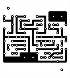
The circuit is best built on a printed circuit board. Refer to my article on the subject, Making Excellent Printed Circuit Boards. Here is the printed circuit layout for the charger:
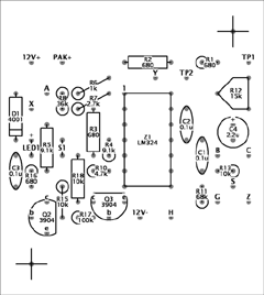
The holes in the top left and bottom right corners are for mounting, and should be drilled out to 1/8" for 4-40 bolts. The holes in the middle of the large copper areas (corresponding to the points labelled 12V+, PAK+, 12V-, and H in the component layout diagram below) should be drilled to 5/64" to accept tinned 14 gauge stranded wire.
The following diagram illustrates component placement on the board:
Note that not all the components are on the board. R9, S1, Q1, and R14 are attached to the enclosure, and connected to the board by wires.
Start by installing all the resistors and capacitors, soldering them in place. Keep all the components as low as possible (especially the resistors that stand on end). Next install D1, Q2, and Q3. Install a socket for Z1. Solder short lengths of stiff wire (cut-off component leads work great) into the holes marked TP1 and TP2. These wires will be a convenient place to attach the test leads of a voltmeter during calibration later.
Temporarily install the board in the case (the board should be held off the floor of the case with a 4-40 nut under each mounting hole). Install LED1 in the appropriate holes, and slide it down until it is at the right height to protrude through the lid once the lid is installed. Carefully remove the board and solder the LED in place. Again, refer to the photos.
Off-board Components
The temperature sensors, start switch S1, and current control potentiometer are all connected to the board using servo lead wire (available at many hobby shops in 10 foot lengths).
Using a short length of servo lead wire with the brown (or black) lead removed, connect S1 to the holes marked S1 on the board.
Connect R9 to the board with another short length of servo lead, connecting the red wire to the right hand terminal (as viewed from the shaft side, with the terminals towards you). Connect the orange (or white or yellow) wire to the centre terminal, and the brown (or black) wire to the left hand terminal. Connect the other ends of the red, orange, and brown leads to the points marked A, B, and C respectively on the board.
Prepare a 2 foot length of servo lead, and solder the red, orange, and brown leads to the points marked X, Y, and Z respectively. About 1 foot from the end, connect a thermistor (TRa) between the brown and orange leads. At the end of the cable, install the second thermistor (TRb) between the red and orange leads. The length of brown lead between TRa and TRb can be removed, since it’s not used. Cover both thermistors with clear heat shrink tubing to take the strain off the connections and protect them from damage. Be careful that the thermistor leads don’t touch one another.
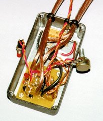
Off-board components are mounted to the case and attached to the board with appropriate gauge wires.
Final Wiring
Throughout all of the instructions below, refer to the photos to assist you in making the right connections. Please note that the circuit board in the photo to the right is a prototype, with a slightly different component layout, but the location of the connection points is approximately the same.
Solder a length of orange, white, or yellow servo lead wire to the hole marked G, and a length of brown or black servo lead wire to the hole marked S.
Solder a length of black 14 gauge flexible wire into hole H, and leave it long enough to reach the left side of R14. Next, solder the 12V input wires to the 12V+ and 12V- holes, and the positive charge lead into the PAK+ hole.
Install the board in the case, being sure that none of the connections short against the bottom of the case (I put a few layers of electrical tape under the board just to be sure).
Connect the lead from hole H to the left side of R14. Connect a short length of red 14 gauge wire from the right side of R14 to the rightmost lead of Q1 (it helps to have clipped off the centre lead of Q1, as it’s not used). Connect the wire from hole G to the leftmost lead of Q1. Connect the wire from hole S to the right side of R14.
Install a lug connector on the end of the PAK- lead, and bolt it to the same bolt that holds Q1 to the charger case.
Solder a pair of heavy duty alligator clips to the 12V+ and 12V- leads, colour coded red for 12V+ and black for 12V-. Solder your favorite battery pack connectors (e.g. Anderson Powerpole, Deans Ultra Plug, Astroflight Zero-Loss, etc.) to the charging output leads.
Calibration
Double check all your wiring. If everything is okay, install Z1 in its socket, being sure to put it in the right way around. Then, connect the input leads to a 12V lead-acid battery. LED1 should glow faintly. If it comes on full brightness, disconnect everything and re-check your wiring.
Make sure the two thermistors are at room temperature, and connect a digital voltmeter to TP1 and TP2 (red lead to TP1, black to TP2). Adjust R12 until the meter reads 0.32V.
Final Assembly
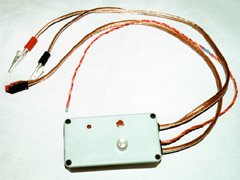
Drill the case top for R9, LED1, and S1. The only hole whose location is critical is that of LED1, since the hole must line up with the LED on the circuit board. R9 should end up approximately over the MOSFET’s leads, as close to the edge of the case as will fit. S1 should end up opposite R9, close to the other edge. The finished charger should look like this (I painted the case top grey):
Testing
Connect a discharged pack to the charge leads, with an ammeter in-line so you can monitor the charging current (an Astroflight Whattmeter works really well for this). Insert the temperature probe into the pack through a hole in the heat-shrink covering at one end of the pack. The probe should be inserted a few inches into the pack, so that the sensor is near the centre of the pack and away from the effects of external air entering through the hole.
Turn the charging current knob fully counter-clockwise, and press the start button (the LED should light). Turn the knob clockwise until the current reads approximately five times the pack’s capacity (for example, 12A for a 2.4Ah pack).
Monitor everything carefully. When the pack is about 2/3 charged (after about 7 minutes), the charge current should drop to approximately half of the initial current. After another 6 minutes or so, the current should drop again. About 2 minutes later, the current should drop to about 100mA, and the LED should turn off, indicating that charging is complete. The pack should be warm to the touch, but not hot. If the pack becomes hot during testing, disconnect it, and troubleshoot the charger.
To calibrate the charger, start with a discharged pack again, and rotate the knob while monitoring the charging current. Mark the desired currents on the case next to the pointer of the knob.
Parts List
The following table lists all the parts needed. Radio Shack® part numbers are provided for those parts available there. The thermistors used in the prototype are from Radio Shack, although almost any thermistor with a 3% to 5% resistance drop per 1°C temperature rise will do.
| Part | Description | Radio Shack® |
|---|---|---|
| R1,R2,R3,R16 | 680Ω ¼W | |
| R4,R5 | 9.1kΩ ¼W | |
| R6 | 1kΩ ¼W | 271-1321 |
| R7 | 2.7kΩ ¼W | |
| R8 | 36kΩ ¼W (or two 18kΩ in series) | |
| R9 | Small 1kΩ potentiometer | |
| R10 | 4.7kΩ ¼W | 271-1330 |
| R11 | 68kΩ ¼W | |
| R12 | 15kΩ trimmer potentiometer | |
| R13,R15,R18 | 10kΩ ¼W | 271-1335 |
| R14 | 0.02Ω 25W | |
| R17 | 100kΩ ¼W | 271-1347 |
| TRa, TRb | Thermistor (10kΩ at 25°C, 4%/°C) | 271-110 |
| C1,C2,C3 | 0.1µF 50V | 272-1069 |
| C4 | 2.2µF Tantalum | |
| D1 | 1N4001 | 276-1101 |
| LED1 | High-brightness LED | 276-87 |
| Q1 | IRL2203N or SMP60N03-10L | |
| Q2, Q3 | 2N3904, 2N4401, or 2N2222 | 276-2016, 2058, or 2009 |
| Z1 | LM324 quad op-amp | 276-1711 |
| S1 | SPST momentary pushbutton | 275-1547 |
| Case | Hammond 1590B |
Parts not available at Radio Shack can be ordered from electronic supply houses such as Sayal Electronics or Digikey.
Related Articles
If you've found this article useful, you may also be interested in:
- BattMan II: Computer Controlled Battery Manager
- USB Powered AA NiMH and NiCd Battery Charger
- Low Cost Thermal Peak Detection NiCd Charger
- LED Bargraph Optical Tachometer
- On/Off Motor Controller with Brake
- Analog Bar Graph Expanded Scale Voltmeter
- Versatile Miniature High-Rate ESC with BEC and Brake
- Miniature High-Rate Speed Control with Battery Eliminator Circuit (BEC)
- Miniature High-Rate Speed Control with Brake
- Getting the Most from Your Radio Control System

If you've found this article useful, consider leaving a donation in Stefan's memory to help support stefanv.com
Disclaimer: Although every effort has been made to ensure accuracy and reliability, the information on this web page is presented without warranty of any kind, and Stefan Vorkoetter assumes no liability for direct or consequential damages caused by its use. It is up to you, the reader, to determine the suitability of, and assume responsibility for, the use of this information. Links to Amazon.com merchandise are provided in association with Amazon.com. Links to eBay searches are provided in association with the eBay partner network.
Copyright: All materials on this web site, including the text, images, and mark-up, are Copyright © 2025 by Stefan Vorkoetter unless otherwise noted. All rights reserved. Unauthorized duplication prohibited. You may link to this site or pages within it, but you may not link directly to images on this site, and you may not copy any material from this site to another web site or other publication without express written permission. You may make copies for your own personal use.
Tom
January 07, 2008
1) I always read from many sources and thought that NiCd batteries cannot (or should not) be charged with current surpassing "10%" of their nominal capacity. So, for i.e. 600mAh (old AA) it should be 60mA. Is this really only about terminating charging just in time? …Or there need to be enough time for proper chemical reaction to store electrical energy. Please respond to the email address above
Stefan Vorkoetter
January 07, 2008
NiCd batteries shouldn’t be charged higher than the C/10 rate only if your charger doesn’t have automatic charge termination. In other words, the C/10 rate is the rate at which it doesn’t matter if you leave them connected to the charger too long (although if you leave them indefinitely, that’s not good for them).
If you have a charger that is guaranteed to stop when the battery is fully charged, you can charge at much higher rates. Exactly how high depends on the battery. The NiCd batteries typically used to power electric R/C models can readily be charged at 4C with a peak-detection charger. That translates to about a 15 minute charge. Regular consumer NiCds can easily be charged at a C/2 or 1C rate, giving a 2+ or 1+ hour charge.
In my experience, NiCds charged with a proper peak-detection or thermal cut-off charger tend to last far longer than ones that are always slow charged and typically left connected to the charger for too long. It’s not uncommon for
Gary Hartman
April 24, 2012
Hi Stefan,
Great site!
Can this application work with the radio tx/rx batteries?
Transmitter:
9.6V (8 cells), 600mAh
Regular Charge Rate: 50mAh for 15 hours
Fast Charge Rate: 150mAh for 5 hours
Gary Hartman
Stefan Vorkoetter
April 24, 2012
Gary, no, it won’t work with those, as they aren’t designed to withstand very high charge rates. However, something like my BattMan II battery analyzer can safely charge those in about 2 hours. BTW, if you have 600mAh Tx/Rx batteries, it’s probably time to replace them, as they’re probably at least 10 years old. I use 2000mAh Sanyo Eneloops in my Tx, since they have 3+ times the capacity, and can sit for months without going dead.
Gary Hartman
April 24, 2012
I’d like go with the Sanyo option but the tx is not set up for single cells. The radio is an Futaba 6EXP but it still works well. I’ll try the BattMan II, the NiCad batteries are still available. Thanks again for the information!
Fred
May 16, 2013
Hi Stefan,
I am very Thankfull for all of your Teriffic electronics work. I would like to ask that you make the Diags. Just a little larger, so that an old man (myself) may be able to read them. I enjoyed reading them. I particularly liked the spade connector fuse holder, but I have to ask -wouldn’t a AGC metal, solder on fuse holder be just as easy ? So – Please keep up the greate work, I’d love to buy you a coffie but at this point in my life I would have to make it for you myself.
Have a Very Nice Day &
Thank You Very Much.
Sincerely
Fred
Stefan Vorkoetter
May 16, 2013
I’m glad you like the articles Fred. Not sure if you know this or not, but you can click on any photo or diagram to display a much larger version.