Build an Analog Bar Graph Expanded Scale Voltmeter
December 29, 2000 for Sailplane & Electric Modeler Magazine
An expanded scale voltmeter (ESV) can save your plane. That may be a strong statement, but it’s true. The crucial radio link that lets you control your plane relies on nickel-cadmium (NiCd) batteries in the transmitter and receiver. If either of these batteries goes dead, you’ll lose control and your plane will likely crash or fly away.
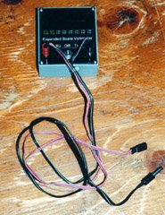
The completed ESV, with test lead plugged in. My test lead has two cables, one for testing receiver packs, and one for transmitter packs.
Unlike carbon-zinc or alkaline cells, NiCd cells have a very flat discharge curve. This means that their output voltage remains relatively constant (ranging from about 1.28V down to 1.17V) until they are almost dead, and then drops off suddenly. Testing the voltage with an ordinary analog voltmeter is therefore nearly useless, because it will always read close to 1.2V no matter how much charge is left.
A digital volt meter would be a slight improvement, because it has enough resolution to show the changes in this narrow range. However, another characteristic of NiCd cells is that they tend to show full voltage when they aren’t doing anything, even if they are almost completely dead. If you use a resistor to discharge a NiCd cell to 0V (this is not recommended), and then remove the resistor and wait a few minutes, measuring the voltage will still indicate about 1.2V.
What is an ESV?
An ESV does two things that an ordinary voltmeter does not.
First, it acts like a magnifying glass on part of the scale of an ordinary meter, namely the part of the scale we are interested in. For example, an ESV for testing a single NiCd cell would range from 1.17V at one end of the scale to 1.28V at the other end of the scale. With the full scale covering this narrow range, it’s easy to see voltage changes within the range.
Secondly, and ESV applies a known load to the cells while it’s testing them. Only by testing them while they are doing a known amount of work can one accurately get an estimate of their state of charge (just like you can’t assess your cardiovascular fitness by measuring your pulse and breathing while you are resting).
Instead of an analog meter movement or a digital display, the ESV described in this article uses a bar graph display consisting of eight LEDs. If no LEDs are lit, the NiCd battery being tested is dead. If all the LEDs are lit, it is close to fully charged.
A switch selects the number of cells being tested, either four for receiver batteries, or eight for transmitter batteries. The vast majority of receiver and transmitter batteries consist of AA cells, and this ESV is calibrated for those types of cells (larger, lower-resistance cells will show a higher voltage for a given load than will the smaller cells).
How it Works
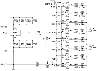
The battery being tested is connected to the “+” and “-” inputs. Depending on the setting of switch S1, the battery voltage is applied across just R1a through R1d (to test a 4-cell battery), or also R2a through R2d (to test an 8-cell battery). This will put a load of approximately 200mA on the battery.
The voltage across the R1 resistors is what will be tested. When testing four cells, this is the full battery voltage. When testing eight cells, it is half the battery voltage, because the R2 and R1 resistors together form a voltage divider. The test voltage is applied to one input of each of the eight voltage comparators Z1a through Z2d.
The other input of each comparator is connected to a point on an 8-way voltage divider, made up of R4 through R10. R3 and Zener diode D1 form a stable voltage reference to supply this voltage divider. R20 sets the voltage at the top of the divider, and R11 and R21 set the voltage at the bottom. R20 and R21 should be adjusted to give 5.13 and 4.66V at the top and bottom respectively.
Whenever the test voltage exceeds the divider voltage at a given comparator, the comparator’s output goes low, lighting the corresponding LED. So, if the test voltage exceeds 5.13V, all the LEDs will light. If it is less than 4.66V, none of the LEDs will light.
Resistors R4 through R10 were chosen to produce voltages that are evenly separated in time along the battery’s discharge curve. In other words, if four LEDs light, it means half the available operating time has been used up, which is not necessarily the same as the voltage being half way between 4.66V and 5.13V.
Power for the entire circuit is provided by a 9V alkaline battery. Since S1 is a center-off momentary toggle switch, power is only used when actually testing a battery, so the 9V battery will last a long time.
Resistors R12 through R19 were chosen to limit LED current to about 10mA. Most LEDs can handle 30mA, but the comparators can only sink at most 16mA, and the lower current levels lengthen the life of the 9V battery.
Construction
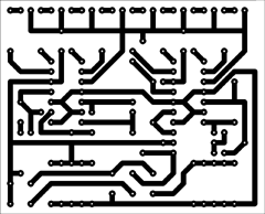
I’ve provided a printed circuit board layout for those who wish to build that way. My article, Making Excellent Printed Circuit Boards, gives tips on etching your own boards. Alternatively, you could build the ESV on a general purpose circuit board, or even a perforated board using point-to-point wiring.
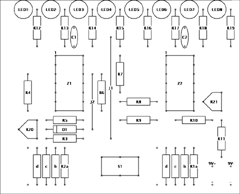
Start by installing wire jumpers J1 and J2.
Select resistors for R1a through R2d. Either use 1% tolerance resistors, or hand pick from a larger selection of 5% resistors to find those closest to 100Ω. What is most important is that the combined parallel resistance of R1a through R1d be equal to that of R2a through R2b.
Next install R1a through R2d. After doing this, measure the resistance across R1a with a digital Ohm-meter. Repeat for R2a. If they aren’t within 1% of each other, you’ll need to install a compensating resistor in the extra set of holes of the group with the higher resistance. The value of this adjusting resistance should be RH x RL / (RH – RL), where RH is the higher of the two resistances, and RL is the lower of the two. For example, if you measured R2 as 26Ω and R1 as 25Ω, then RH is 26, RL is 25, and the adjusting resistor to be installed next to R2d would be 26 x 25 / (26 – 25), which is 650Ω. The closest commonly available value is 680Ω, which will do fine.
Install R3 through R21, C1, and C2. Next install D1, making sure the banded end is adjacent to R20. Install sockets for the two integrated circuits.
Next install the eight LEDs. They will have a flat spot on one side, and this flat spot should be adjacent to the corresponding resistor (to the right on the component layout diagram). Depending on the enclosure you intend to use, you might want the LEDs to stand up fairly high to reach to (or through) the front panel.
Connect a 9V battery clip to the 9V+ and 9V- inputs, with the red lead at 9V+. Connect an appropriate test lead to the “+” and “-” inputs. In my prototype, I made a pair of banana jacks out of pieces of brass tubing, but you can also solder the test leads directly to the circuit board. My test lead has two plugs on the end, one for the transmitter charging jack, and one for the receiver charging jack. Be sure to check your transmitter’s documentation as to the polarity of the charging jack; it varies from brand to brand.
Finally, install S1. This is most easily done by first soldering short lengths of solid hook-up wire to the switch terminals, and then inserting these into the holes in the circuit board.
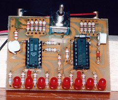
The completed circuit board. The prototype used vertically mounted trimmer potentiometers rather than the more convenient horizontally mounted ones in the parts list. Notice the extra adjusting resistor installed in the R1 group.
Calibration and Testing
Do not install Z1 and Z2 in their sockets yet. Connect a 9V battery to the battery clip. With S1 in its center-off position, nothing should happen.
Turn both R20 and R21 to approximately their midpoints. Clip the black lead from a digital voltmeter to the 9V- lead (the easiest way to do this is to clip the voltmeter lead to J2). Connect the voltmeter’s red lead to the center terminal of R20 or the top end of R4 (the end furthest from R20). While holding S1 in either of its two on positions, adjust R20 until the voltmeter reads 5.13V.
Next, move the voltmeter’s red lead to the center terminal of R21 or the rightmost end of R10 (the end closest to R21). Adjust R21 until the voltmeter reads 4.66V. Now move the red lead back to R20, and readjust R20 to give 5.13V. Repeat this, going back and forth between R20 and R21, adjusting for 5.13V and 4.66V respectively. After going back and forth a few times, you should have both voltages correct. Disconnect the digital voltmeter.
Install Z1 and Z2, being careful to put them in the right way around. Connect a fully charged 4-cell receiver battery to the ESV’s test leads. With S1 switched to the receiver position (to the left), all eight LEDs should light. With S1 switched to the transmitter position, none of the LEDs should light.
Next, connect a fully charged 8-cell transmitter battery. With S1 switched to the transmitter position, all eight LEDs should light. Avoid switching S1 to the receiver position when testing a transmitter battery or R1a through R1d will overheat.
Try testing the transmitter battery when it’s installed in the transmitter, by plugging the test lead into the charging jack. If you can’t get the LEDs to light, it could be that your transmitter has a reverse polarity protection diode in it. If so, you’ll need to bypass this diode. Most modelers bypass it with a small fuse, so the reverse polarity protection is still there, but the battery voltage can be tested without removing the battery from the transmitter.
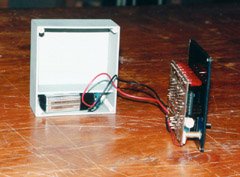
I attached the board to a smoked transparent front panel (using the switch to hold it in place). One of the brass tubes used as a banana jack is visible near the bottom. The enclosure is home-made, complete with a compartment for the 9V battery.
Enclosure
The ESV can be installed in a variety of enclosures. I constructed one from gray plastic, with a smoked transparent plastic cover. That way, the only holes I needed to drill were for the switch, test leads, and screws. The LEDs are visible through the cover, even in daylight. If a professional appearance is not important, you could even just cover the whole circuit in clear heatshrink tubing and hold the 9V battery to the backside with Velcro® or servo tape. Regardless of the enclosure you use, I’ve provided a suitable front panel label that you can photocopy and glue on.
Using the ESV
I use my ESV every time I go flying, and part way through the day when spending a long time at the field. I’ve found its estimates of remaining charge to be fairly accurate, as confirmed by measuring the remaining capacity at the end of the day by discharging at a known current.
If four or less LEDs light, I start testing more often (before each flight). If two or less LEDs light, I won’t fly without recharging the offending battery first.
In addition to indicating remaining charge, an ESV can also provide an early indication of some kinds of problems. If a fully charged battery lights less than eight LEDs, figure out why. Possibilities include a poor connection in a switch, a broken power lead or cell-to-cell connection (with only pressure still holding things together), corrosion, a bad cell, or voltage depression (caused by prolonged overcharging). In all cases, there is a disaster waiting to happen, and the problem should be rectified.
Please remember however that an ESV is not a substitute for regular battery and wiring inspections. If a connection is intact but is about to break, the ESV will give no indication that anything is wrong.
Parts List
The following table lists all the parts along with DigiKey part numbers. Radio Shack part numbers are also shown for those parts available at your local Radio Shack store.
| Part | Description | DigiKey Part | Radio Shack Part |
|---|---|---|---|
|
R1a…R1d, R2a…R2d |
100Ω ¼W resistor |
100QBK-ND |
271-1311 |
|
R3 |
2.2kΩ ¼W resistor |
2.2KQBK-ND |
271-1325 |
|
R4 |
1.2kΩ ¼W resistor |
1.2KQBK-ND |
|
|
R5 |
330Ω ¼W resistor |
330QBK-ND |
271-1315 |
|
R6 |
390Ω ¼W resistor |
390QBK-ND |
|
|
R7 |
470Ω ¼W resistor |
470QBK-ND |
271-1317 |
|
R8, R9, R12…R19 |
680Ω ¼W resistor |
680QBK-ND |
|
|
R10 |
1kΩ ¼W resistor |
1KQBK-ND |
271-1321 |
|
R11 |
39kΩ ¼W resistor |
39KQBK-ND |
|
|
R20, R21 |
10kΩ trimmer |
3316F-103-ND |
271-282 |
|
C1, C2 |
0.1uF capacitor |
P4923-ND |
272-109 |
|
D1 |
1N5232 5.6V 500mW Zener |
1N5232ADICT-ND |
|
|
LED1…LED8 |
Red LED |
P300-ND |
276-041 |
|
S1 |
DPDT center-off momentary toggle switch |
CKN1129-ND |
275-620 |
|
Z1, Z2 |
LM339 quad comparator |
LM339N-ND |
276-1712 |
|
Miscellaneous |
9V battery clip |
BS6I-ND |
270-325 |
Related Articles
If you've found this article useful, you may also be interested in:
- BattMan II: Computer Controlled Battery Manager
- LED Bargraph Optical Tachometer
- On/Off Motor Controller with Brake
- High Speed NiCd Charger for Electric R/C
- Versatile Miniature High-Rate ESC with BEC and Brake
- Miniature High-Rate Speed Control with Battery Eliminator Circuit (BEC)
- Miniature High-Rate Speed Control with Brake
- Getting the Most from Your Radio Control System
- Low Cost Thermal Peak Detection NiCd Charger

If you've found this article useful, consider leaving a donation in Stefan's memory to help support stefanv.com
Disclaimer: Although every effort has been made to ensure accuracy and reliability, the information on this web page is presented without warranty of any kind, and Stefan Vorkoetter assumes no liability for direct or consequential damages caused by its use. It is up to you, the reader, to determine the suitability of, and assume responsibility for, the use of this information. Links to Amazon.com merchandise are provided in association with Amazon.com. Links to eBay searches are provided in association with the eBay partner network.
Copyright: All materials on this web site, including the text, images, and mark-up, are Copyright © 2025 by Stefan Vorkoetter unless otherwise noted. All rights reserved. Unauthorized duplication prohibited. You may link to this site or pages within it, but you may not link directly to images on this site, and you may not copy any material from this site to another web site or other publication without express written permission. You may make copies for your own personal use.

phanindra
April 18, 2008
Can we use this circuit for transmitting data and voice from a helicopter to ground station through satellites?
Chris Michael Galo
February 27, 2010
Do you have a dc power supply design with an output of 3.3V and 5V fixed and a variable power supply from 1-12V? This is for a 3-output power supply with a low current rating being used in the transformer because I want to have a power supply casing as small as possible. Thank you and more power.
Stefan Vorkoetter
February 27, 2010
No, sorry, I don’t have such a design.
Nazionel
April 25, 2011
For me is more important such circuits,I add my project.
thamk you
Deni Flores
August 27, 2011
Can this be modified to indicate analog bar representation for a diy bench psu? i would love to monitor 3v, 4.5, 6, 9, 12, 15, 18, 24 (8 LEDs) volts.