Chord EGG 2015: Remaking a PAiA Classic
December 23, 2015
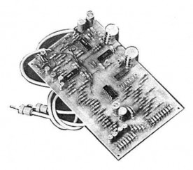
The Stereo Chord EGG was a novel little circuit introduced in kit form by PAiA in 1976 as an interesting application of a top octave generator IC. This chip, which was state-of-the-art at the time, generated a whole octave plus one note (C8 to C9) on its 13 outputs from a single high frequency input (2MHz). Its main application was in electronic organs, where the outputs were fed into frequency dividers to produce a full range of pitches (e.g. C1 to C9) at various footages. This was a big improvement over earlier electronic organs that had a separate oscillator for each top octave pitch, which could drift out of tune relative to each other.
In the Chord EGG, the top octave generator was used in a slightly different way. The Chord EGG fed it a much lower frequency input (125kHz) to directly generate the octave from C4 (middle C) to C5. These notes were combined into chords (F, G, and two inversions of C). The circuit played a random sequence of these chords, each for a random length of time. Another part of the circuit randomly varied the amplitude of each note in the chord as it played. Finally the chord was fed into two voltage controlled filters (VCFs), each under the control of its own randomly varying control voltages. The filter outputs were the left and right channels of the stereo output of the Chord EGG.
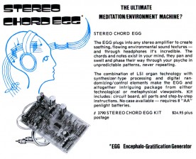
The whole effect was to “create soothing, flowing environmental sound textures … The chords and notes EXIST in your mind, they pan and swell and phase their way through your psyche in unpredictable patterns, never repeating.”
I suspect that only a small number of Chord EGG kits were produced and sold. Although the design and implementation are interesting, the EGG is ultimately a novelty, having few obvious practical applications. At a cost of $24.95 USD in PAiA’s 1978 catalog (about $91 of today’s dollars), it likely found few buyers.
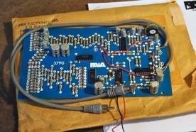
This is borne out by the relative rarity of the Chord EGG on eBay compared to other PAiA gear from that period. When they do show up, like the one shown here courtesy of eBay seller electrosignment, they sell for far more than their inflation-adjusted price would suggest (this one sold for $220 USD).
Now, almost 30 years later, I’ve thought of an application. I wanted to replace my glowing red LED radio alarm clock with an analog one. What I did not want was a jarring BEEP-BEEP-BEEP alarm, nor did I want to continue waking to voices on the radio. The Chord EGG sprung to mind as an interesting alternative source of “music”.
The only flaw with this plan is that Chord EGGs are hard to find, as already mentioned. Being the DIY sort, building one from scratch is the obvious answer. Unfortunately, top octave generator chips are equally hard to find, and very expensive when they do pop up.
Instead, I elected to design a new circuit, based on the existing one wherever possible, but deviating where necessary. One other goal I set myself was to produce a design that could have been built using the technology available in 1976.
I’d like to take this opportunity to thank the folks on the PAiA Talk forum, where I received both encouragement and answers to my questions about the functioning of the original Chord EGG.
A Brief Look at the Original Chord EGG
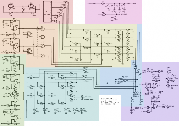
Below is the complete schematic of the original Chord EGG, reproduced here with the kind permission of PAiA, with the major subsystems highlighted:
The following is a brief description of the function of each subsystem. For a more detailed description, please refer to this abridged version of the PAiA 3790 Stereo Chord EGG manual (reproduced here with the permission of PAiA).
Tone Generator
The tone generator consists of an oscillator at approximately 125kHz (not 250kHz as described in the manual), feeding an MK50240 top octave generator IC. Eight of the 13 outputs of this IC provide the notes C4, D, E, F, G, A, B, and C5. Due to the inaccuracy of the simple oscillator, the octave could start on any note (or even between two notes), but the frequency relationship between them will still be that of a major scale.
Chord Randomizer
This section consists of two very slow op-amp square wave oscillators with periods of about 15 and 25 seconds, effectively generating a 2-bit binary number. This is then decoded into one of four outputs by an array of CMOS NOR gates (although they are drawn incorrectly as OR gates).
Chord Decoder
The outputs from the tone generator and chord randomizer are combined using an array of resistors. At any given time, only one column of the array is high, resulting in tones appearing on the three rows connected to that column by resistors. On the right hand side of this section, the eight note rows are combined into four with at most one note from each chord appearing on each of the four outputs.
Note Randomizer
Like the chord randomizer, the note randomizer uses slow oscillators running at different speeds. Unlike the chord randomizer where exactly one output is on at any given time, the outputs of the note randomizer oscillators are used directly, meaning that any combination of the four outputs (including none or all of them) can be on at the same time.
Control Voltage Summing Matrix
This very large array of resistors and capacitors mixes the four note randomizer outputs to produce six separate control voltages. The capacitors slow down the transitions when the note randomizer state changes, resulting in six seemingly random slowly varying voltages.
Voltage Controlled Attenuators
The four outputs from the chord decoder (three of which will have tones on them at any given time) are fed into another small resistor array that attenuates the notes based on another set of control voltages. Four outputs from the summing matrix are used to control the amount of each note signal that makes it to the filter. The effect is that the individual notes of the chord currently playing fade in and out.
Voltage Controlled Filters
The remaining two outputs from the summing matrix are used to control the pass bands of two simple voltage controlled filters. Both filters receive the same audio signal as input, but since their pass bands are controlled separately, the relative amplitude at which the harmonics of a given note make it through the filters varies.
Power Supply
The Chord EGG is designed to run from a single 12V power supply. This is filtered by a resistor and several capacitors (spread throughout the circuit on the actual board). A separate supply with its own filter provides the 12V reference voltage needed by the oscillators.
The Redesign
As mentioned previously, the MK50240 top octave generator is no longer made, and is quite hard to find for a reasonable price. Likewise, the LM3900 Norton (current differencing) op-amps used for the low frequency oscillators are also out of production, so a design change was required there as well.
Tone Generators
At first glance, one approach to replace the top octave generator would be to use a PIC or similar micro-controller, but generating eight notes simultaneously is a task for which a PIC is probably not fast enough. An alternative approach would be to implement the tone generator, chord randomizer, and chord selector together in a PIC, in which case it would only need to generate the three currently playing notes simultaneously, which might be achievable.
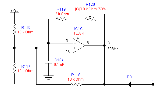
However, I really wanted to build this entire remake using parts available in the 1970s, so I adopted the same approach that electronic organs used before top octave generators became available: separate oscillators, one for each top octave note.
Each generator is a simple relaxation oscillator built around one quarter of a TL074 quad op-amp. I’m not sure this chip existed in the 1970s, but the pin-compatible (and in this application, functionally compatible) LM324 quad op-amp did, as I have a 1976 National Semiconductor databook describing it.
An advantage of using separate oscillators is that they can be tuned arbitrarily. Instead of the (approximately) equally tempered scale produced by a top octave generator, I was able to tune to Ptolemy’s Intense Diatonic Scale, a form of just intonation, where the frequencies of all the notes are related by ratios of small integers. This results in purer sounding chords, due to the absence of beat frequencies within the audible range.
To choose the component values for each oscillator, I used my trusty HP-67 programmable calculator (1978), running an an oscillator design program that I wrote for it.
Chord Randomizer
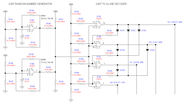
Redesigning the two low frequency oscillators of the chord randomizer to use standard op-amps was easy, but that left the issue of how to decode the resulting 2-bit number to one of 4 outputs. I could have used a pair of quad CMOS NOR gates like in the original design, but that would have required one and a half chips, leaving two unused gates (in the original design, these implemented the 125kHz clock for the top octave generator).
Instead, I came up with what I think is a rather interesting design. The 2-bit number from the two oscillators is fed into a simple digital to analog converter consisting of resistors R145, R150, R151, and R152. The resulting voltage, which can take on one of four values, is then fed into a 4-stage level detector build around four op-amps (IC3A to IC3D) used as comparators.
Diodes D101 to D106 provide feedback from the outputs of the three highest stages to the inputs of each of the lower stages to ensure that only the detector corresponding to the current voltage level is on, and all the ones below it are off. This is analogous to the “dot” mode versus the “bar” mode of the popular LM3914 dot/bar display driver IC.
Note Randomizer
Like the oscillators of the chord randomizer, the note randomizer oscillators were redesigned using standard op-amps.
Voltage Controlled Filter
Once again, standard voltage-differencing op-amps were substituted for the current-differencing Norton op-amps of the original design. Unlike the oscillators, the filter circuit did not require a redesign, as it works identically with either type of op-amp.
Everything Else
The chord decoder, control voltage summing matrix, and voltage controlled
attenuators were left almost exactly as in the original design. The only change
was that 680Ω attenuation resistor R57 was replaced with a 5kΩ
trimmer potentiometer to allow adjustment of “presence”.
An interesting outcome of the redesign is that it uses the same number of ICs as the original (five), but instead of one specialized LSI chip, two CMOS quad NOR gates, and two quad Norton op-amps, the redesign uses five identical readily available TL074 (or LM324) chips! This came at the cost of 52 extra resistors, 8 more capacitors, and half a dozen diodes.
Here are links to the complete set of schematics:
- Chord Randomizer, Decoder, and Attenuators
- Tone Generators
- Note Randomizer, Control Voltage Matrix, and Filters
Construction
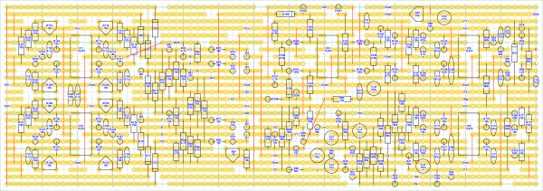
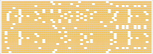
The original Chord EGG kit was supplied with a printed circuit board with the component locations silk-screened on the upper side. For the Chord EGG 2015, I decided to use stripboard, my favourite one-of-a-kind construction technique. I’ve found that for circuitry involving many long-leaded passive components such as resistors and diodes, stripboard allows for reasonably high component density without the need for an excessive number of jumper wires.
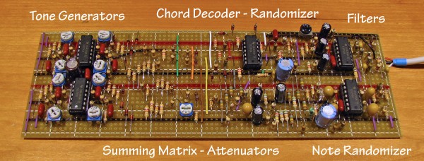
Here is the stripboard layout, shown from the component and copper sides:
The various subsystems are reasonably self-contained in their own areas of the board:
Parts List
For those who want to try to reproduce this circuit, here is a complete parts list. All resistors are rated 1/4W, and all capacitors are rated 16V or higher:
| Designator | Value | Quantity |
|---|---|---|
| C2, C3, C4a, C4b, C101-108 | 0.1µF | 12 |
| C11-14, C111-114 | 33µF | 8 |
| C15, C16, C24 | 100µF | 3 |
| C17 | 47nF | 1 |
| C18-21 | 10nF | 4 |
| C23 | 2.2µF | 1 |
| C109, C110 | 47µF | 2 |
| D1-14, D101-106 | 1N914 | 20 |
| R27, R30, R34, R38, R41, R42, R45-48 | 56kΩ | 10 |
| R28, R31, R35, R36 | 270kΩ | 4 |
| R29, R32, R33, R37, R39, R40, R43, R44, R53-56, R172 | 150kΩ | 13 |
| R49-52, R58, R61-81, R85, R96, R101-103, R106-109, R111-113, R116-118, R121-123, R126-128, R131-133, R136-138, R141, R146, R150, R151, R165-167, R169-171, R173-175, R177-179 | 10kΩ | 69 |
| R57 | 5kΩ trimpot | 1 |
| R82-84, R86, R87, R142, R145, R152 | 4.7kΩ | 8 |
| R88, R92 | 82kΩ | 2 |
| R89, R93, R158-161, R180 | 100kΩ | 7 |
| R90, R94 | 680kΩ | 2 |
| R91, R95 | 68kΩ | 2 |
| R97, R105, R110, R115, R120, R125, R130, R135, R140 | 10kΩ trimpot | 9 |
| R98, R99, R154-156 | 2.2kΩ | 5 |
| R104, R147, R153 | 8.2kΩ | 3 |
| R114, R119 | 12kΩ | 2 |
| R124 | 15kΩ | 1 |
| R129, R134 | 18kΩ | 2 |
| R139, R162-164 | 22kΩ | 4 |
| R143 | 3.3kΩ | 1 |
| R144 | 470kΩ | 1 |
| R148 | 6.8kΩ | 1 |
| R149 | 390kΩ | 1 |
| R157 | 2.7kΩ | 1 |
| R168 | 220kΩ | 1 |
| R176 | 330kΩ | 1 |
| IC1-5 | TL074 | 5 |
Tuning
Unlike the original, which was automatically in tune with respect to itself, this version requires tuning of the individual notes. The easiest way to do this is with an accurate frequency counter (one with at least 4½ digits of precision and 0.2% accuracy). I have one that is an order of magnitude less precise and accurate, so this would have resulted in the notes being badly out of tune.
This is where just intonation saves the day. Because the pitches of the notes in such a scale are related by ratios of small integers, the tone generators can be tuned either by ear, or using an oscilloscope in X-Y mode.
First, I tuned the A note using a frequency counter (part of a cheap Radio Shack multimeter) connected to pin 14 of IC1D. I also used the frequency counter to pre-tune the remaining notes to their approximate frequencies.
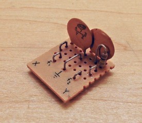
Tuning using an oscilloscope is done by generating Lissajous figures. Unfortunately, this doesn’t work with the square wave outputs of the oscillators (all the figures just look like a square), so I had to construct a pair of simple low-pass filters to produce a slightly smoother waveform. Each tone generator was tuned by connecting the X-input of the scope (through the low-pass filter) to an already tuned note, and the Y-input to the note to be tuned.
The following table gives the ratios between pairs of notes to be tuned, each row depending on the tuning of the previous rows to be completed:
| Tune Note … | … Using | Ratio | Frequency |
|---|---|---|---|
| A | 440Hz | ||
| F | A | 4:5 | 352Hz |
| C5 | F | 3:2 | 528Hz |
| C4 | F | 3:4 | 264Hz |
| E | C4 | 5:4 | 330Hz |
| G | C4 | 3:2 | 396Hz |
| B | G | 5:4 | 495Hz |
| D | G | 3:4 | 297Hz |
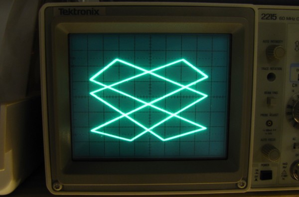
A note that is perfectly in tune produces a stable image on the oscilloscope display, like this one while tuning C5 using F:
The number of points on the side of the figure corresponds to the left hand side of the ratio (3 in this example), and the number of points along the top corresponds to the right hand side of the ratio (2 here). If the tuning is very slightly off, the figure will seem as if it is a cylinder, rotating either horizontally or vertically. The further from correct the tuning is, the faster the cylinder will spin.
How Does it Sound?
I wasn’t really sure what to expect before hearing it the first time, as the only recording of a Chord EGG I’d ever found was extensively post-processed. When I first connected an amplifier (a set of amplified PC speakers) and turned it on, I could hear the occasional note drifting in and out of audibility, but most of time there was silence. After some debugging, I concluded that the voltages from the chord randomizer differed from the original design due to the op-amp based 2-bit to 4-line decoder instead of the CMOS one. I determined that increasing the value of R57 would likely fix the problem. To make it easier to experiment, I replaced the 680Ω fixed resistor with a 5kΩ trimmer to allow for easy adjustment.
After making that small change, the circuit just worked as described in the original documentation. It really needs to be heard to be appreciated, so here is a two minute recording:
Conclusion
This was an enjoyable exercise in re-engineering a 1970s design, using 1970s technology. As I mentioned near the beginning of this article, the ultimate plan was to make this part of an alarm clock, which I have since done.
Related Articles
If you've found this article useful, you may also be interested in:
- MusicRack – A Digital Sheet Music Display System
- Building a Musical Sunrise Quartz Alarm Clock
- Oh, the Noise! Noise! Noise! Noise! – Stringz’n’Thingz Revisited
- Rejuvenating and Expanding a PAiA 1550 Stringz’n’Thingz Synthesizer
- Retronome – A Versatile Analog Drum Machine for My Hammond Organ

If you've found this article useful, consider leaving a donation in Stefan's memory to help support stefanv.com
Disclaimer: Although every effort has been made to ensure accuracy and reliability, the information on this web page is presented without warranty of any kind, and Stefan Vorkoetter assumes no liability for direct or consequential damages caused by its use. It is up to you, the reader, to determine the suitability of, and assume responsibility for, the use of this information. Links to Amazon.com merchandise are provided in association with Amazon.com. Links to eBay searches are provided in association with the eBay partner network.
Copyright: All materials on this web site, including the text, images, and mark-up, are Copyright © 2025 by Stefan Vorkoetter unless otherwise noted. All rights reserved. Unauthorized duplication prohibited. You may link to this site or pages within it, but you may not link directly to images on this site, and you may not copy any material from this site to another web site or other publication without express written permission. You may make copies for your own personal use.


Robert
May 17, 2016
I built one of these in high school. I wish I still had it. I ran it into my first Koss headphones, no amp. Pretty low level, but ok for going to sleep. I too have an ebay search for these! No joy so far.
Are the diodes still 1N914 devices? Is there a parts list for your “new and improved” EGG? I wonder if it is possible to tune it by ear? I play violin, viola, sing, and have perfect pitch. I also own a 440Hz tuning fork, and an electronic tuner that clamps to my instrument.
I think I’ll build one of your updated units, after I finish my HAL9000 fisheye lens computer terminal, from the old movie 2001.
Where did you source your parts?
Stefan Vorkoetter
May 17, 2016
They come up on eBay from time to time, but are quite expensive when they do. I suspect most people buy them just to salvage the top-octave chip.
If you have a good ear, which it sounds like you do, then tuning it be ear should be no problem, especially if you want to use just intonation, where all the frequency ratios are small fractions. First tune A to the fork, and then tune the other frequencies just like I did, but using your ear instead of an oscilloscope.
I’ve just added a parts list to the article. I tend to buy parts in large lots from eBay sellers, so I’m not really sure which parts came from where, but if you want to buy just the parts for this project, DigiKey would be a good choice.
I’m curious about your terminal. I’m familiar with HAL and 2001, but what exactly will your terminal do?
Robert
May 18, 2016
Thanks for the parts list.
My HAL is a full scale resin kit. It came with a clear plastic dome, HAL9000 decal, a LED light kit for the red dot you see in the lens in the movie, a speaker, and a sound sample chip with a bunch of HAL sound clips you can trigger. I decided I wanted a real fisheye lens instead of a badly simulated lens. Then I decided I could attach a small CCD security type cam to the lens. I have an old portable DVD player with a yellow RCA composite video input to let me see through the fisheye. I might add an intercom circuit.
The true original Nikon lens used in the movie is nearly as rare as an original Chord EGG board, and much more expensive! $2,000 or more for a scratched example. My Nikon fisheye is newer, for a discontinued digital camera (I forget the model), and I got two of them for about $100. The front curve of the glass is not as dramatic as the correct lens, but that is ok. It looks pretty good, and is the correct diameter for the model, and is a functional lens. I haven’t decided how to mount it. The neck of the lens and attached camera will stick out the back of the resin casting. I have pretty much everything I need, including the lacquer paints, but have a few more decisions to make, so all the parts are sitting in a box waiting for me to locate my round tuit. No rush!
I thought about attaching it next to my front door, to examine people who ring my doorbell. My bell sounds a foghorn noise, like on The Addams Family. My mail lady loves it! But I don’t want it stolen, so I will just find a place for it near my computer.
Tom Kinahan
November 30, 2016
Hi – thanks very much for your article. I’ve been keen to reproduce the original PAIA 3790 for a few years now and would love to find an original board or a scan of the PCB – would you have any access to that?
I have several MK 50240 chips and there is also the “FK50240 Top Octave Synthesiser Chip” available from Flatkeys http://www.flatkeys.co.uk/MK50240.html
They also make transpose and scale switches which I’d love to try out. There is an old mod in Polyphony which I will dig up that produces minor chords as well.
Thanks, Tom Kinahan, Kelowna, BC
Stefan Vorkoetter
December 08, 2016
Unfortunately I have neither a board, nor a scan of one. I have a scan of the manual, but the copper side of the board layout isn’t in it.
Dave
July 03, 2017
I have a reprint from Radio-Electronics with the copper side and 2-mod files.
If your going to make circuit boards let me Know?
Stefan Vorkoetter
July 03, 2017
I’m not planning on making circuit boards, for the original nor my version. It’s nearly impossible to get parts for the former, and I doubt enough people would be interested in building the latter (or the former for that matter).
B Oliver
September 05, 2017
I have a couple of M083 top octave dividers, and would like to build a Chord EGG someday. I have all the documentation, including the PCB designs. Id be interested in chatting with anyone who would also like to get a PCB done up.
Tom Kinahan
September 13, 2017
Hey B Oliver and Dave – if you have a scan of the original PCB I’d be interested – I have two TOD’s, one in original Radio Shack bubble packaging, so would like to try both the original and the Stefan version…
Tom Kinahan, Kelowna, BC
william holland
October 14, 2017
Hi, Thanks for the additional input. I went thru the EGG parts list and it differed slightly from the schematic. I revised my parts copy to follow the schematic. I thought you would like my findings. Remove R110 from the 10K list as it is a trimpot. There is no R59 10 ohm that I could find in the schematic or the parts location board. R153 is a 8.2K and listed in parts as a 4.7K(qty 9 S/B 8 and the 8.2K upped to 3 from 2), and finally R157 is a 2.7K listed in parts as a 1K. Thanks again, Bill
Stefan Vorkoetter
November 02, 2017
Thanks for finding the parts list errors. You are correct on all counts, and I’ve updated the list in the article. Regarding R59, that was a resistor in the original Chord EGG that wasn’t needed in the remake, but accidentally got left on the parts list.
Brandi Weed
March 07, 2018
Where do you get such a big piece of stripboard?
Stefan Vorkoetter
March 07, 2018
It was from a seller on eBay, I don’t recall who though. Just search for stripboard or veroboard. Look at the listings carefully though, since many are just pad-per-hole, or breadboard-like layouts. I think the pieces I got were 4.5×10 inches. Here;s a link to some 7×12 inch boards: https://www.ebay.com/itm//222760133347