A Compact Home-Made Raspberry Pi Tablet
June 28, 2017
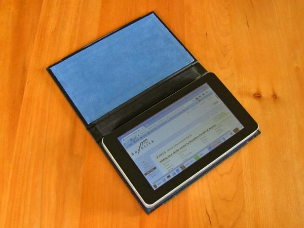
Although a software developer by day and tech hobbyist by night, I’ve never been into buying every new gadget that comes out. I got my first smartphone in 2015, and have so far resisted getting onto the tablet bandwagon, perhaps because I’m often at or near a computer anyway, rendering a tablet redundant.
I recently got to try an Android tablet for a few days but found it too limiting due to the closed nature of most of the software available for it. Around the same time, I discovered the Raspberry Pi 3 and its matching 7″ touchscreen, and realized I could build a nice Linux tablet completely to my liking based on those, so that is what I set out to do.
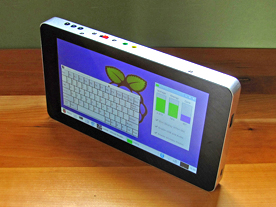
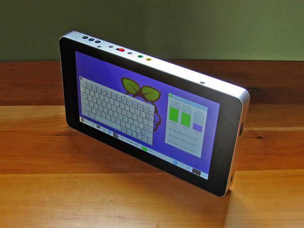
Mine certainly isn’t the first Pi-based tablet, as Googling “Raspberry Pi Tablet” will reveal, but I believe it to be the smallest and lightest so far:
- CPU: Raspberry Pi 3B with 1.2GHz quad core ARMv8 and 1Gb RAM
- Storage: Lexar 32Gb micro-SD card
- Display: 7″ 800×480 multi-touch capacitive touchscreen
- Audio: On-board with 25mm speaker, and built-in USB with mic and earphone jacks
- Ports: One external full-sized USB port, micro-USB port for charging
- Operating System: Raspbian Jessie
- Dimensions: 195 × 112 × 17.6 mm (7 11/16 × 4 3/8 × 11/16″)
- Weight: 484 g (17.1 oz)
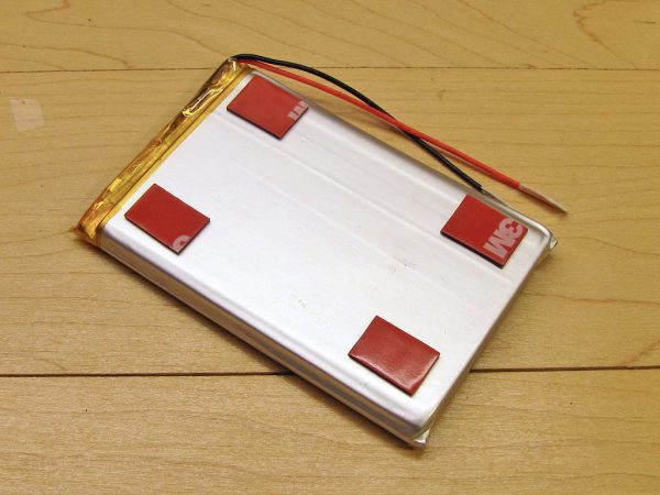
- Battery: 6200mAh LiPoly, giving 4 to 12 hours battery life (6 hours watching YouTube)
To build such a compact device, I had to heavily modify the two major components and get creative about how to arrange them. This also necessitated a custom enclosure.
In contrast to most of my projects, I did not plan everything out in advance. I very much, “made it up as I went along”, and this article is as much about the journey as it is about the result. If you want to build a tablet like mine, consider this article a rough guide, as there are no complete plans. The photos are approximately in chronological order, although I did do some jumping back and forth between sub-tasks during the actual construction.
Components
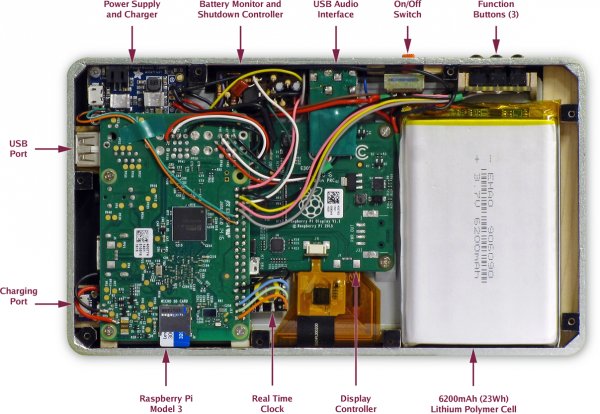
The components used in this project are:
- Raspberry Pi model 3B with a 32Gb SD card
- Official Raspberry Pi 7″ touchscreen
- Adafruit Powerboost 1000C charger and 3.7-to-5V converter
- DS3231 temperature compensated real time clock
- USB audio adapter
- PAM8302-based mono class D amplifier
- 25mm 8Ω speaker
- Battery monitor and shutdown control circuit
- 6200mAh Lithium-polymer battery
- SPDT slide switch and 3 small pushbutton switches
- USB and micro-USB ports
Trimming the Fat
The Raspberry Pi is very small, but not small enough to squeeze into such a tiny package. The combined thickness of the Pi and display when assembled as recommended is about 40mm (1 9/16″). I reduced this considerably by mounting the Pi beside the display controller instead of on top of it, and by removing a few unneeded large components from both the Pi and controller.
Raspberry Pi
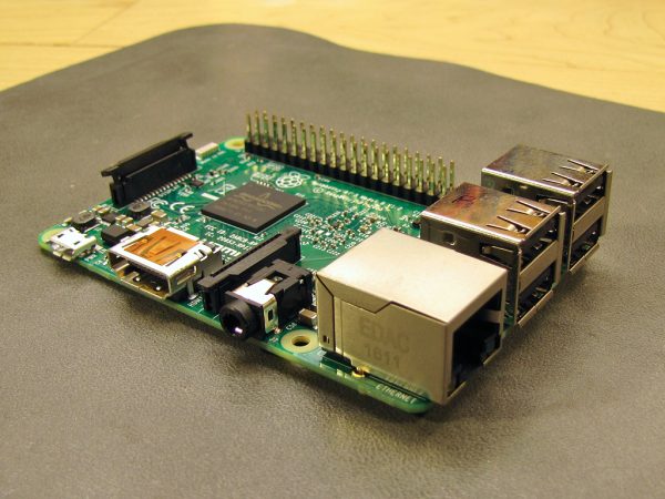
The tablet would not make use of the wired Ethernet port nor the on- board USB ports, and since these both use a lot of space, I removed them.
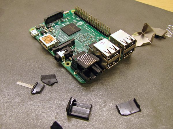
I removed the Ethernet and USB ports by peeling off the metal shielding, cutting the plastic, and unsoldering the remaining pins.
Although the tablet makes extensive use of the GPIO pins, everything is hard-wired, so the space-consuming header was unnecessary.
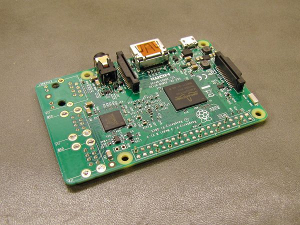
All the GPIO pins except the ground pins were unsoldered. The ground pins were later clipped shorter.
Display
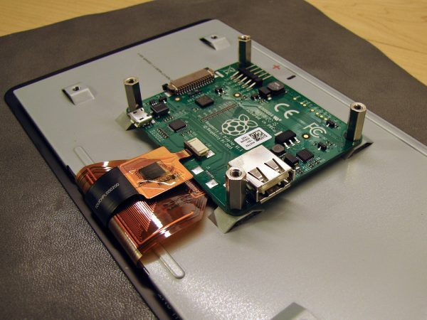
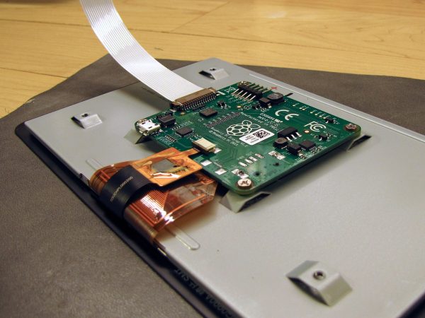
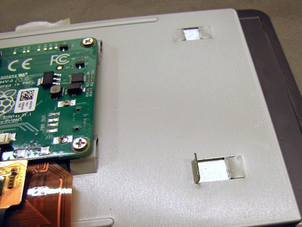
The display is designed for the Raspberry Pi to be stacked on top of the controller board, an arrangement that is about 40mm thick. Since I would be mounting the Pi adjacent to the controller, the tall standoffs could go. The USB power output port is also useless (it doesn’t even provide 5V when the display is powered from 5V), so I unsoldered it too.
The mounting tabs would interfere with the Pi on one side of the display controller and the battery on the other side, so I removed them. I first cut through each one at the centre with diagonal cutters, then bent it up slightly to cut the centre sections off of the sloped sections. The latter were then folded down flush with the metal plate.
The Case
With both the Pi and display controller thinned down, I experimented with various standoffs to see how close to the back of the display I could mount the Pi (still partially overlapping the controller). I eventually arrived at 16mm (5/8″) as the amount of interior space I would need to fit everything comfortably.
I decided that the overall width and height should be just a tiny bit bigger than the screen itself, just enough to protect the glass edges from impacts.
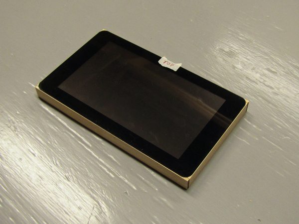
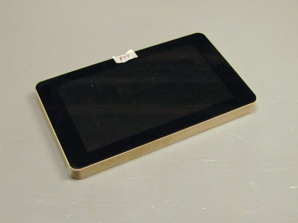
The case consists of three parts. The front is the touchscreen itself, the back is a piece of 0.8mm fiberglass (unclad circuit board material), and the two are separated by a 16mm thick frame.
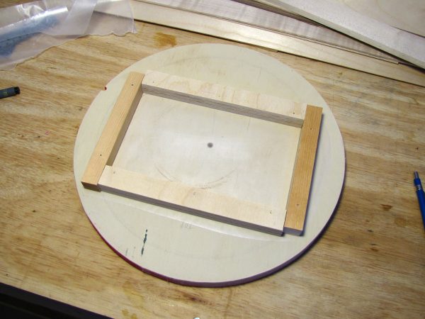
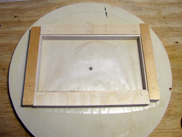
To construct the frame, I began by building a jig on a piece of very flat plywood left over from another project.
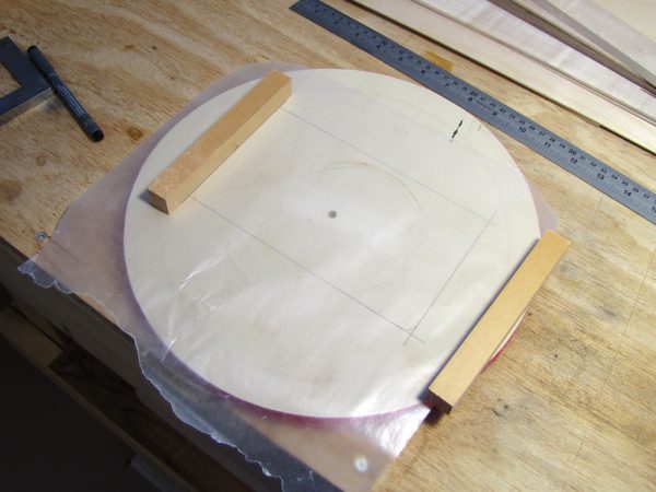
The jig was constructed on a piece of very flat plywood. The wax paper is to prevent the frame from sticking to the jig.
I built the frame inside the jig from solid maple, cut into strips 16mm wide and 2.8mm thick (there is nothing special about the thickness; I just happened to have thin maple of this thickness on hand).
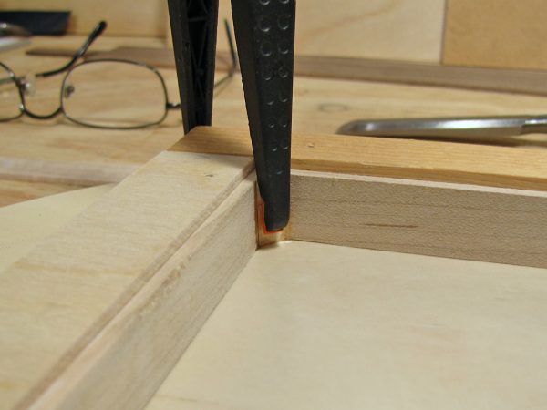
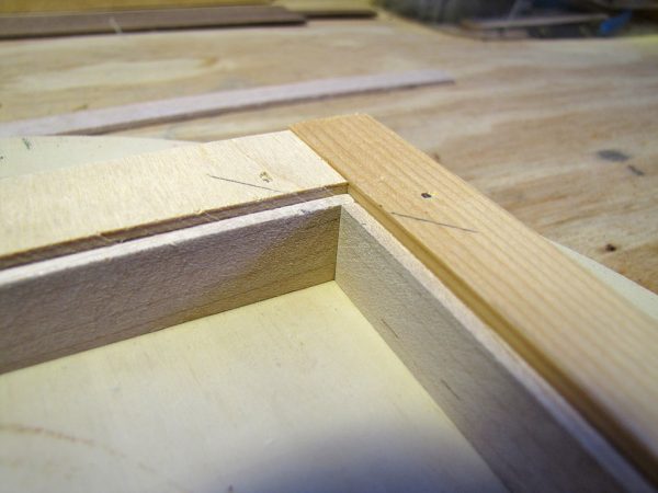
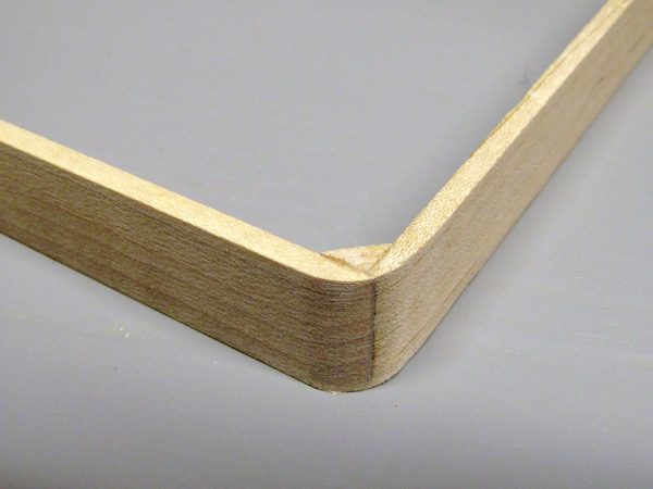
After the corner joints cured, excess epoxy was chiseled off, and the corners reinforced with triangular blocking.
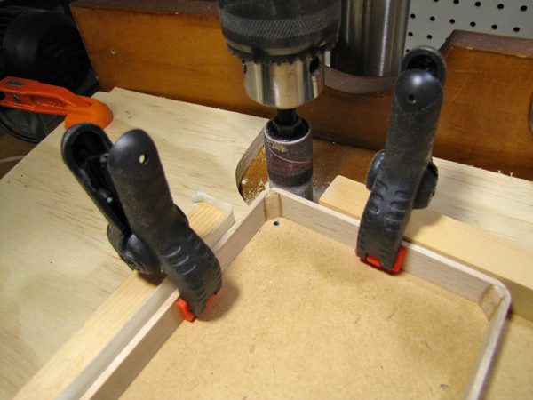
The corners were rounded to about an 8.5mm radius. To do this precisely and consistently, I built another jig to hold the frame, first for rough cutting on the bandsaw, and then sanding to shape with a sanding drum. I designed the jig to pivot around the centre of curvature.
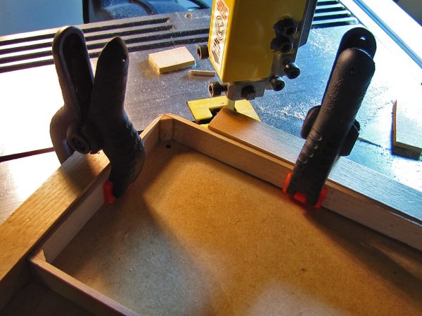
I constructed another jig to hold the frame for rounding the corners, first by cutting them roughly to shape.
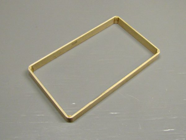
The completed frame was remarkably sturdy, despite being held together only by small triangular blocks and epoxy in the corners (the stuff is strong enough to glue airplanes together). No additional bracing was needed, since the display and case back would provide the necessary structure to prevent the frame from flexing.
The case needs holes cut in it for the power switch, buttons, and various ports, but I deferred this until I knew exactly where all these parts would end up.
Attaching the Pi to the Display
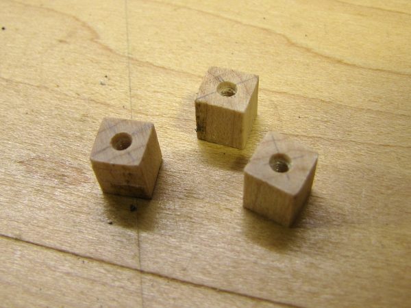
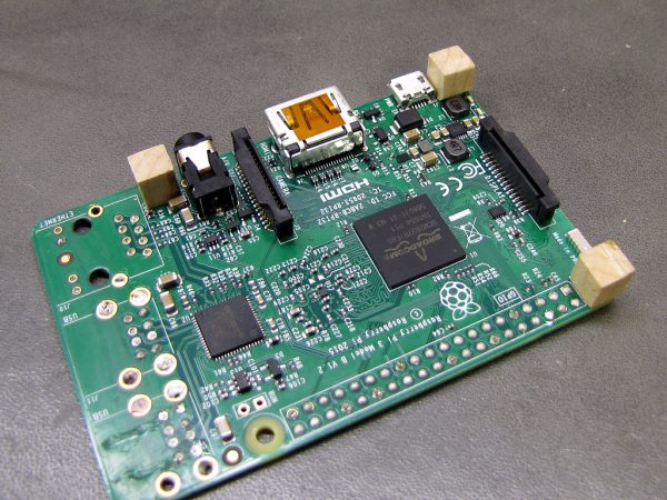
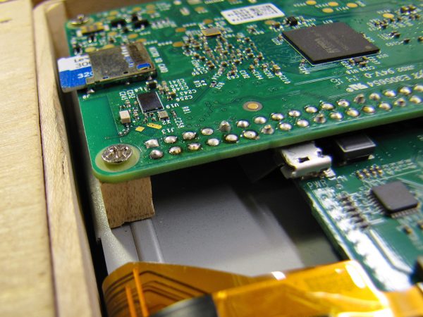
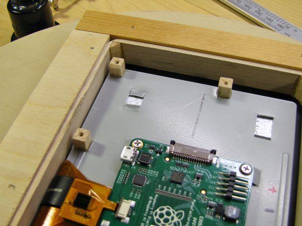
I mounted the Raspeberry Pi face down on three standoffs cut from 5mm (3/32″) square maple blocks, each 8mm (5/16″) long. After fashioning the blocks, they were screwed to the board with M2.5x4mm screws, and then epoxied to the metal display back.
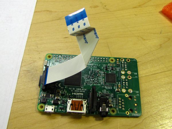
Because of the unusual mounting position of the Raspberry Pi relative to the display controller, I had to slightly trim the ribbon cable at the Pi end (so it could bend closer to the board), and fold it as shown below to connect it to the controller.
Positioning the Display in the Frame
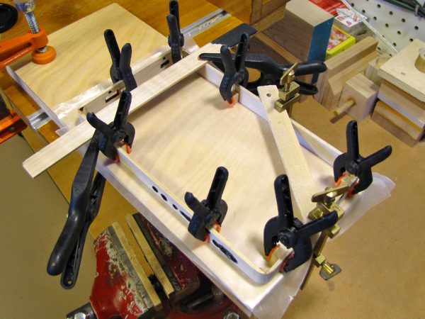
To keep the display in the correct position in relation to the frame, I fashioned a series of spacer blocks to fit between the metal display back and the wooden frame. These were then epoxied to both the metal and the back of the glass, thus also preventing any display creep that some users of the touchscreen have experienced. Some of these spacers also double as mounting surfaces for other components.
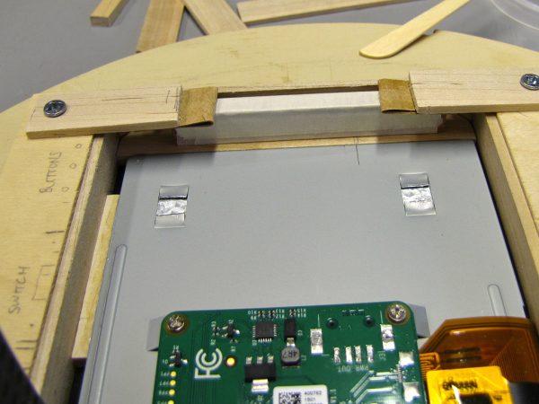
One spacer has already been installed (left), and another is held by clamps (top) while the epoxy cures.
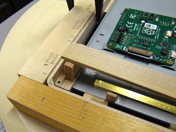
Installing the spacers was done in the frame construction jig to keep everything positioned properly.
All the Other Bits
Once the location of the two major components was cast in stone (or epoxy), I began to play around with the design and/or placement of the other parts.
Power Supply
My tablet is powered by a lithium-ion-polymer battery (whose size I did not choose until I was sure how much space would be left), feeding an Adafruit PowerBoost 1000C. This handy little board contains both a 3.7V-to-5V boost converter that can power the Pi and display, and a lithium ion charge controller. When an external power supply is plugged in, it provides power to both the charger and the system at the same time.
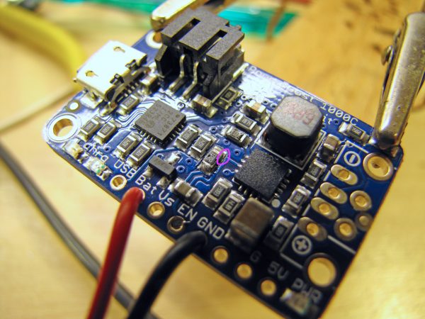
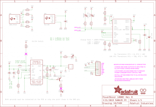
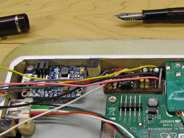
I made a few small modification to the PowerBoost 1000C. As shown in the photo above, I cut the trace to 200kΩ pull-up resistor R13 for compatibility with my shutdown control circuit (described later). This and the other changes are detailed in the modified schematic below:
Due to the confined space with minimal airflow in which the PowerBoost 1000C would be installed, I decided to attach heatsinks to the charging and voltage conversion chips. I made these from thin aluminum sheet, filed the bottom surface flat, and fastened them to the chips with a mixture of epoxy and heatsink compound.
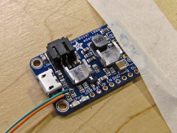
I attached homemade heat sinks to the charging and power conversion chips. The orange and green wires are to allow the Pi to monitor charging status.
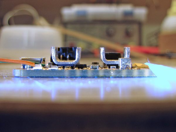
The bottoms of the heat sinks were filed flat before mounting with a mixture of epoxy and heatsink compound.
Function Buttons
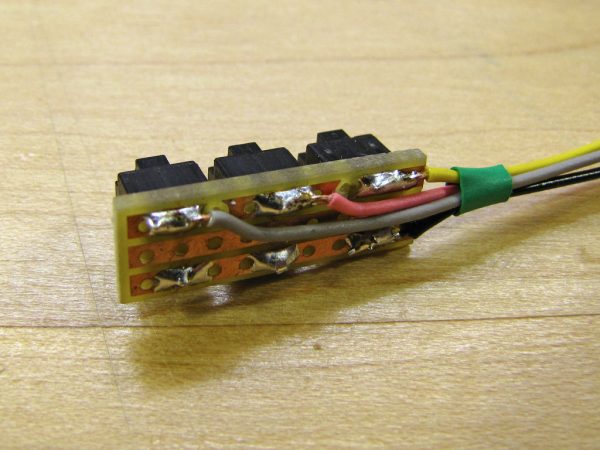
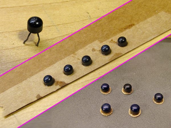
I wanted to have a few (three seemed about right) physical buttons on the tablet to access operations that might sometimes be awkward to perform using the touchscreen, such as bringing the on-screen keyboard to the foreground or maximizing a window. The switches for these buttons were salvaged from a non-working mouse I pulled out of the hardware recycling bin at work.
To make the actual buttons, I cut the legs off of several old (1970s?) transistors I had in my junk drawer, epoxied them to cardboard from the back of a pad of paper, and then used a hole punch to create nice round buttons with a flange at the bottom.
USB Audio and Realtime Clock
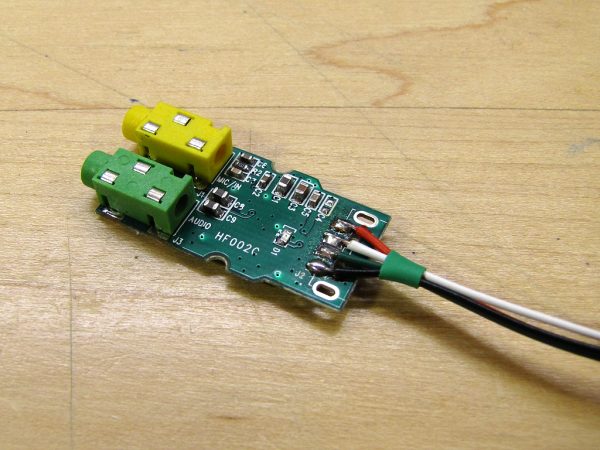
The Pi’s built-in audio is not very good (approximately 11 bits resolution, with poor high frequency response), so I added an aftermarket USB audio adapter for use with earbuds or external speakers. The USB audio also allows for use of a microphone.
I removed the adapter from its case and replaced the USB plug with wires that would be soldered directly to the USB pads on the Raspberry Pi board. I also unsoldered and resoldered the two jacks, which were surface mounted despite the fact that both the jacks and the board were configured for through-hole mounting (which is more secure for something that undergoes repeated physical stress).
The Pi does not have an on-board real-time clock (RTC, really the only thing that it’s missing), so I purchased an external RTC module on eBay. The one I received uses a DS3231 RTC chip, which is identical to the (more common?) DS1307, but features a temperature-compensated crystal oscillator for better long term accuracy. The module is designed to plug directly into the Pi’s GPIO pins, but since I removed the pins, I also removed the socket from the module and replaced it with wires.
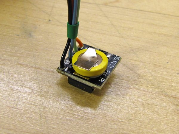
Like the audio adapter, the DS3231 real-time clock’s connector was removed and replaced with individual wires (only 4 of the 5 connector pins are actually used).
Shutdown Controller and Battery Monitor
The PowerBoost 1000C has an enable input, EN, which if pulled low, will turn off the 5V output and put the entire device into a very low power mode. Unfortunately, doing this will not allow the Raspberry Pi to shut down properly. Requiring the user, even though it’s just me, to perform a proper shutdown seemed error prone.
The PowerBoost also has a low-battery warning output (LBO) which can be used to signal the Pi that the battery is almost dead. However, I wanted more precise battery information so that I could display a state-of-charge indication just like an off-the-shelf tablet would have.
To address both of these problems, I designed a small circuit containing both a shutdown controller and a battery voltage monitor.
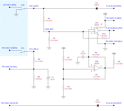
Schematic of the shutdown controller and battery monitor. The blue area is the off-board power switch.
The shutdown circuit consists of DPDT power switch S1, R8, R9, and C1. When the power switch is turned on, C1 quickly charges through S1A and R8, bringing the EN output high and turning on the PowerBoost 1000C after about 0.1 seconds. When S1A is opened (i.e. S1 off), C1 slowly discharges through R9, and after about 20 seconds, reaches a low enough voltage to turn the PowerBoost off. This time delay circuit is the reason why pull-up resistor R13 had to be disconnected on the PowerBoost. With it present, C1 can only discharge to about 4.2V.
When S1 is switched off, S1B will also immediately pull GPIO pin 40 (physical pin number) low through D2, signalling the Pi that power loss is imminent. A daemon monitoring this pin can then initiate a shutdown.
The circuit consisting of Z1A and Z1B, the two voltage comparators of an LM393 dual comparator IC, comprises the battery voltage monitor. Z1B, R1 through R5, and C2 form a triangle wave oscillator oscillating at approximately 100Hz, with low and high peaks at 1.87V and 3.33V respectively. This triangle wave is then compared against a fraction (0.689) of the battery voltage by Z1A, producing a rectangular wave at its output with duty cycle varying from 0% when the battery is at or below 2.72V, to 100% when the battery is at or above 4.83V. This is fed to GPIO pin 38, where the duty cycle is monitored by the daemon.
The PowerBoost’s low battery output (LBO) is connected through D1 to GPIO pin 36 to warn the Pi, via the daemon, that a critical battery situation has been reached and that it should drop everything and shut down immediately.
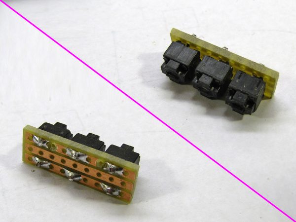
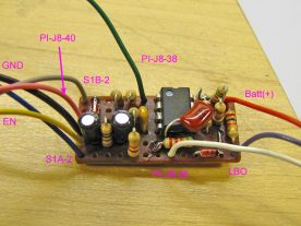
- I built the battery monitor on a small (1.3×0.6″ or 33x15mm) piece of stripboard.
- Completed battery monitor and shutdown controller.
As has become my custom for one-of-a-kind analog circuits, I constructed this on a small piece of stripboard. In the photo above right, there are two electrolytic capacitors, 10µF each and wired in parallel to give 20µF. I would have used a single 22µF capacitor if I’d had a small enough one on hand.
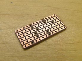
For those wanting to reproduce this board, here is the stripboard layout:
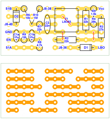
Shutdown controller and battery monitor component placement (top) and stripboard trace layout (bottom). Actual size is 1.4×0.7″ (36×18mm).
Completing the Case
I began by attaching all the display-mounted parts that would require matching holes in the case frame.
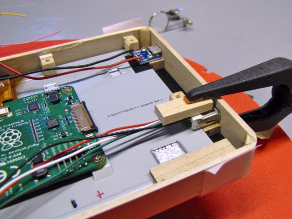
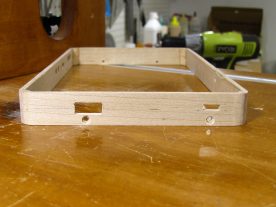
The micro-USB charging port (top) was screwed to a frame spacer, and the full-sized USB port (right) was epoxied to another spacer.
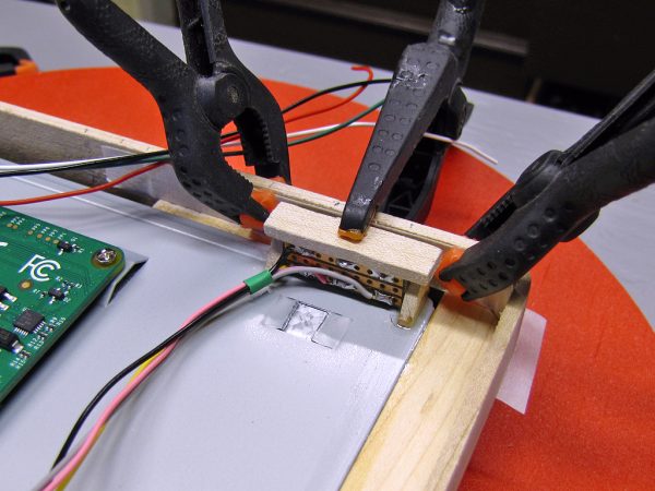
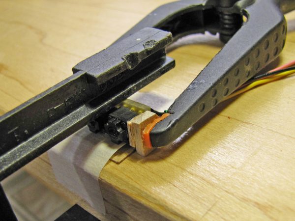
The complete button switch assembly was epoxied to the metal display back, with a piece of thin cardboard ensuring the correct spacing from the frame.
Making Holes in the Frame
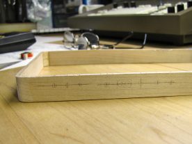
The next step was to make all the necessary holes. I laid out all the remaining parts needing holes, and carefully measured and marked their locations on the outside of the frame. At the same time, I also marked the locations for the screws that would hold the frame to the display.
- The centre of each hole was carefully marked.
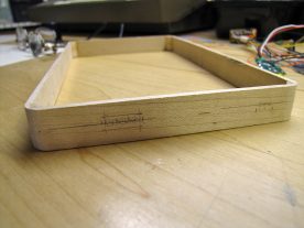
- I made rectangular holes by starting with a series of round holes.
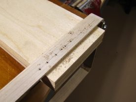
- Each hole was first drilled with a 2mm bit to create pilot holes.
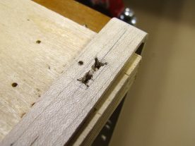
- Part way through making a rectangular hole.
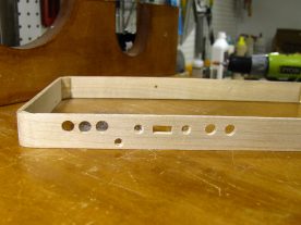
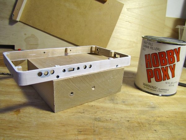
- Completed holes along the top edge of the case, including countersunk screw holes.
- The rectangular holes were finished using a small chisel and files.
Round holes were made using successively larger drill bits so as not to splinter the wood. I made the rectangular holes by drilling a series of round holes, chiseling out most of the remaining material, and finishing the shape with small files and sanding blocks.
The Back Cover
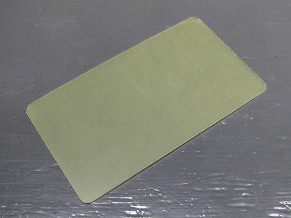
I made the back cover out of a piece of 0.8mm (1/32″) unclad fiberglass circuit board material. I traced around the display directly onto the material and then cut it to size. The straight edges were cut by repeatedly scoring and then snapping the board, and I then rounded the corners by hand, cutting them roughly with tin snips and then sanding them to shape.
The cover is held in place by eight M2.5x4mm screws, countersunk into the cover as far as possible.

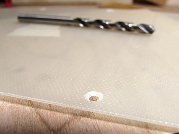
With the translucent back taped in place, I drilled through it at the centre of each mounting block.
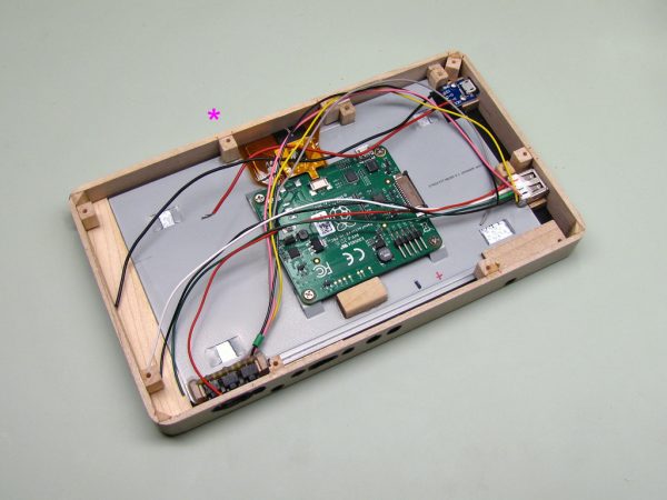
The mounting blocks are visible here. The one marked * is attached to the display, not the frame, and also takes a screw to fasten the frame to the display.
Finishing the Frame
I debated with myself for a long time how I wanted to finish the frame. I considered a natural wood finish, glossy black, and metallic silver. Small defects in the wood that occurred while drilling the holes and were repaired with filler ruled out the natural finish, and I finally settled on the slightly retro look of silver.
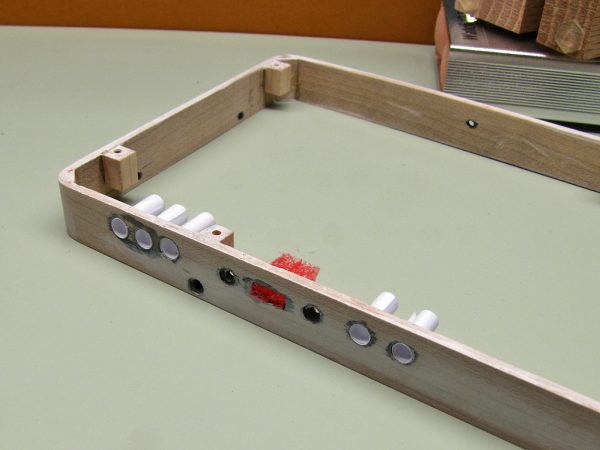
Before spraying the silver coats, I stained all the holes black and plugged them so they wouldn’t fill with paint.
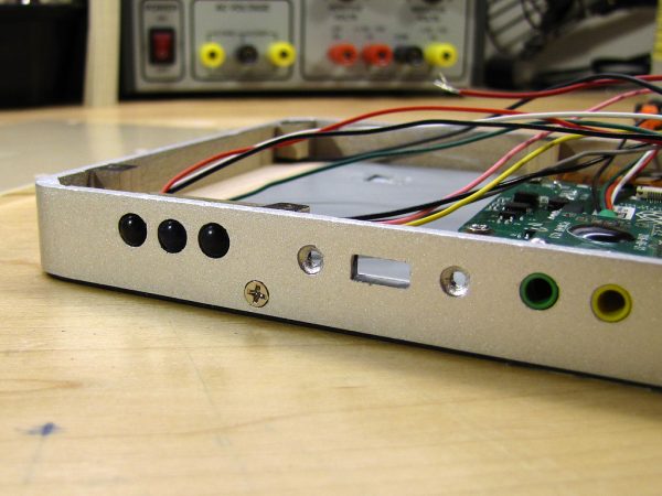
After two coats of Krylon Brilliant Silver and two coats of Clear Gloss, you can’t tell it’s wood any more.
Component Installation and Wiring
At this point, all the parts were completed. All that remained was to put everything together. The two USB ports and the button switch assembly were already attached to the display, but the PowerBoost 1000C, shutdown controller and battery monitor, USB audio adapter, power switch, real time clock, and battery all still needed to be installed.
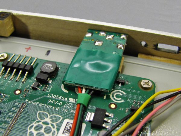
The USB audio adapter is a friction fit. The block, visible under the mid-right side of the adapter, prevents it from moving when a cable is plugged in.
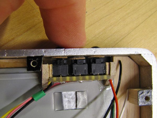
Like the audio adapter, I inserted the buttons from inside the frame before lowering the frame onto the back of the display.
I forgot to take a picture specifically of the PowerBoost 1000C installation. It sits on a small platform in the top-left corner, held in place by one screw, and a small peg to prevent it from rotating. It is visible in several of the pictures below.
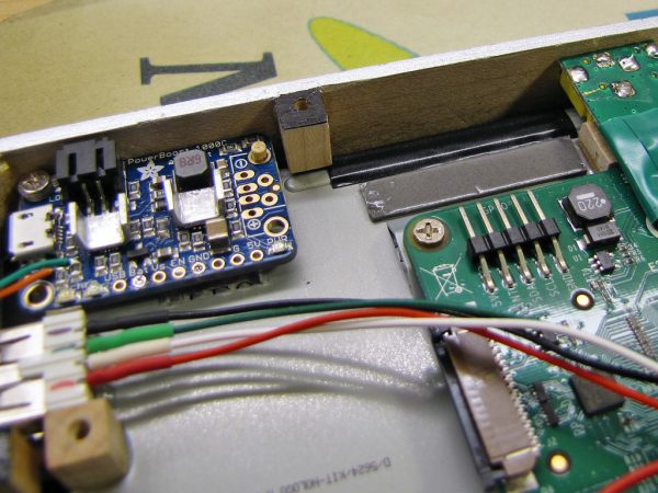
Two layers of electrical tape over the metal ridge serve as insulation, and a piece of auto side moulding mounting tape will hold the shutdown controller and battery monitor in place.
I also neglected to photograph the power switch, which is visible in the wiring photos further below. The switch is a simple DPDT slide switch, with a rather long handle, from my parts collection. Two 3mm thick blocks were epoxied to its mounting ears. These block then take M2.5x4mm screws from the outside of the frame.
After all of the above components were in place, I began wiring them together, since later components would make access difficult. I then installed the Raspberry Pi and completed most of the remaining wiring.
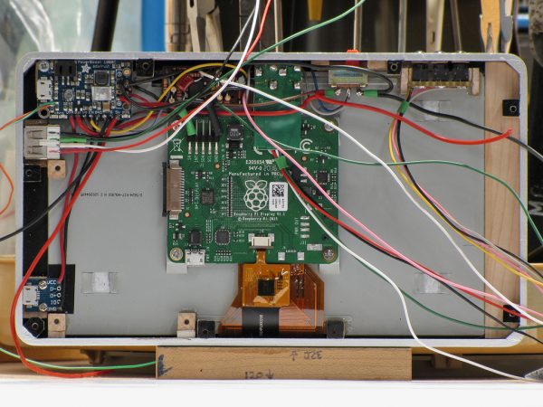
Completed wiring between the PowerBoost 1000C, shutdown controller and battery monitor, power switch, and charging port.

With the Raspberry Pi installed, I completed the power, USB, and GPIO wiring. The real time clock has also been installed and connected (bottom right side of the Pi).
Instead of a fancy Fritzing diagram as seems to be popular for Raspberry Pi and other projects, I hand drew and then followed the wiring diagram below. The parts are obviously not to scale, but are drawn in their approximate relative locations.
More Work on the Case Back
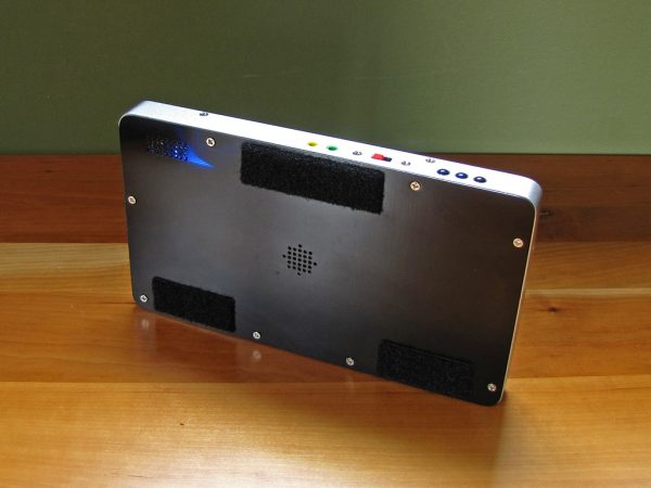
Once all the components (except the battery) were in place, I could mark where I planned to install the speaker and amplifier, drill holes for the speaker and for cooling, and then finish the outside of the case back.
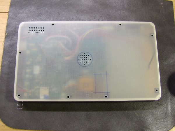
With all the components in place, I marked and drilled the locations of the speaker and cooling openings and marked where the amplifier would go.
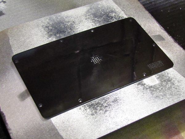
The outside of the back cover was sprayed with two coats of VHT Nite-Shades transparent black headlight paint.
Battery Installation
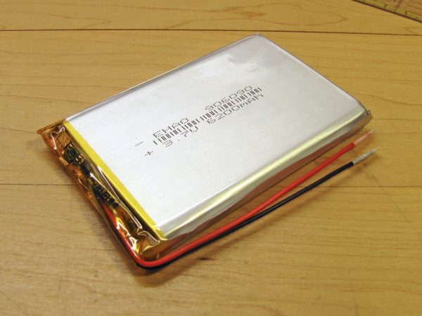
I had ordered the battery from a seller on eBay as soon as I knew how much space I would have, but after three months, it still had not arrived. I contacted the seller, and he shipped a replacement by a faster method, which arrived in just over a week.
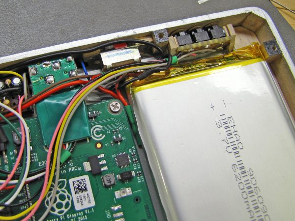
I cut the supplied leads as short as possible to minimize resistive losses, and spliced them to the tablet’s power leads.
Internal Amplifier and Speaker
Although the primary audio output of the tablet is via the USB audio adapter, I wanted to have a built-in speaker for applications like an alarm clock, or watching a YouTube video with a friend. I used a tiny and very thin 2.5W (overkill) class D amplifier, and an equally small 8Ω speaker.
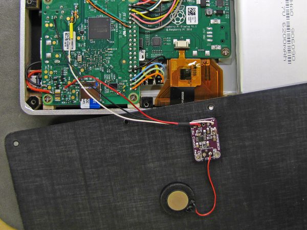
The amplifier was fastened to the inside back cover with mounting tape, and the speaker with its supplied adhesive ring.
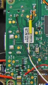
Since there is only one speaker and a mono amplifier, I mixed the left and right audio channels together using a pair of 220Ω resistors soldered to the Pi’s audio jack test points, and fed the resulting signal into the amp. Click on the image to the right to see a close-up of the connections to the Raspberry Pi board.
To avoid damaging the speaker, which can’t handle even close to 2.5W, I turned the amplifier’s physical volume control to zero, played a maximally loud recording at full volume, and then turned the amp up to just below the point where the speaker started to sound unhappy. This ensures that nothing I play through the speaker in the future can damage it, even if I watch Star Trek: Into Darkness on my tablet.
All Done!
After screwing the back cover on, the tablet was done!
Software
My tablet runs Raspbian Jessie, which although a great Linux distro, needs a few additions to be a viable OS for a tablet. I added several pieces of software, some open source, and some that I wrote myself (also open source). I started development of the software early in the project so that I had something to do while waiting for various parts to arrive (I powered the tablet from an external 6600mAh lithium ion battery for a few months).
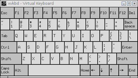
xvkbd
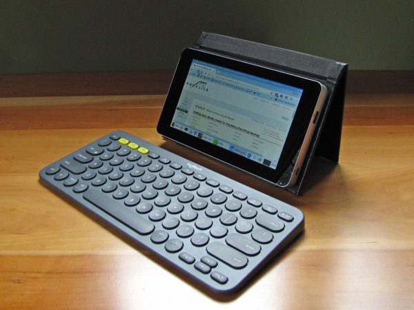
A tablet needs an on-screen keyboard (although I also use it with a
Logitech K380 Bluetooth keyboard for
tasks requiring a lot of typing). I tried a few alternatives,
including
matchbox,
but found them not to my liking. I eventually settled on
xvkbd, customized via the ~/.Xresources file.
twofing
Raspbian treats the touchscreen the same way as a one-button mouse, so common gestures like dragging to scroll or long pressing for a right- click do not work (except in Chromium, which supports these directly). The excellent twofing utility solves all these issues by implementing two-finger gestures for right clicking, horizontal and vertical scrolling, and zooming.
Pi Tablet Daemon
In the construction notes, I’ve made reference to a daemon which
monitors various bits (literally) of the hardware. The daemon, named
pitabd, is written in C and is launched from
/etc/rc.local (at some point I may take the time to configure it
properly as a service). It performs the following functions, once per
millisecond unless otherwise noted:
- checks for a shutdown signal from the power switch and initiates a proper shutdown.
- monitors the three buttons and performs the corresponding actions:
- bring keyboard (short press) or dashboard (long press) to front
- increase brightness by 1/8 (short press) or to maximum (long press)
- toggle foreground application between normal and maximized (short press) or full screen (long press)
- monitors commands from the dashboard (every 5 seconds):
- enable/disable screen dimming on idle when on battery power
- enable/disable USB and Ethernet ports
- enable/disable Wi-Fi and Bluetooth
- power monitoring:
- status of PowerBoost 1000C charging and charge-completed indicators
- battery voltage
- estimate of energy remaining
- information is written to a tiny RAM disk for display by dashboard
- monitors X11 idle time (at varying intervals depending on need):
- dims display to half of selected brightness after 2 minutes of inactivity
- turns off backlight completely after 5 minutes
- monitors PowerBoost 1000C LBO and performs an immediate shutdown if triggered.
The daemon makes use of the following libraries and utilities:
- bcm2835 – low level GPIO library used to monitor buttons, voltage, etc.
- libxss and xscreensaver – allows the daemon to monitor user idle time
- wmctrl – command line utility used by the daemon to resize windows
I’ve made the source code for the Pi Tablet Daemon available under the GNU General Public License at github.com/svorkoetter/PiTabDaemon.
Pi Tablet Dashboard
The dashboard is a small graphical utility that is launched from
~/.config/lxsession/LXDE-pi/autostart to display the
current state of the system, and to allow the user to adjust some
settings. It is written using FreePascal and Lazarus (an open source
Delphi-like RAD environment). The dashboard performs the following
functions:
- displays system status:
- battery voltage
- estimated energy remaining
- CPU/GPU temperature
- lets user adjust power saving settings:
- dim display when idle on battery power
- enable external USB and audio (and the unused Ethernet port)
- enable Wi-Fi and Bluetooth
- displays concise information in its taskbar icon:
- energy remaining both as a gauge and a number
- gauge blinks at 2Hz when energy is below 5%
- blinking lightning bolt at 1Hz indicates charging is in progress
- solid lightning bolt indicates charging is complete
I’ve made the source code for the Pi Tablet Dashboard available under the GNU General Public License at github.com/svorkoetter/PiTabDashboard.
Conclusion
Well, it’s been a long build and a long article. I spent about three months of evenings building this tablet, slowed down from time to time by having to wait for parts to arrive. It has pulled together several of my interests, including electronics, software development, wood working, and just plain tinkering.
The end result is a tablet that is somewhat comparable to commercial offerings in many ways, but is a full blown portable Linux system of about the same power as my travel laptop (and will likely replace said laptop).
This project wouldn’t have been possible without that great little computer and display from the Raspberry Pi foundation, as well as the many add-on bits produced by third parties. And of course, it would have gone nowhere without the huge amount of free software out there, including but not limited to Raspbian (GNU Linux) itself, FreePascal and Lazarus, xvkbd, twofing, and countless other packages that make Linux complete. Without these, I would have been reinventing a lot of wheels.
Addendum February 2018: Adding Better Bluetooth
After successfully using this tablet as a laptop (netbook) replacement I really missed having a mouse. The touchscreen is fine for browsing and e-mail, but tasks like text and photo editing are better done with the higher precision of a mouse.
I ordered a Logitech T630 ultra-thin touch mouse, but found that when I tried to use it together with the keyboard, both the mouse and the keyboard behaved erratically (jerky mouse motions and lost or repeated keystrokes).
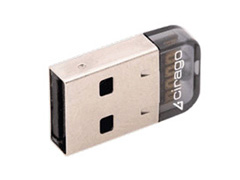
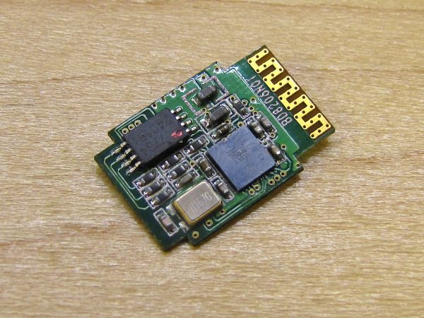
A bit of Googling revealed that this is a known problem with the Pi 3’s built-in Bluetooth, and the only solution is to use an external adapter. I decided to try an old Cirago Bluetooth 2.1 adapter I had lying around, and was pleasantly surprised to find that it worked with Raspbian.Of course, I didn’t want a Bluetooth adapter sticking out the side of my tablet and tying up the only USB port. I followed the the same approach I used with the USB audio adapter, stripping it of it’s casing and wiring it directly to one of the unused ports on the Pi 3 board.
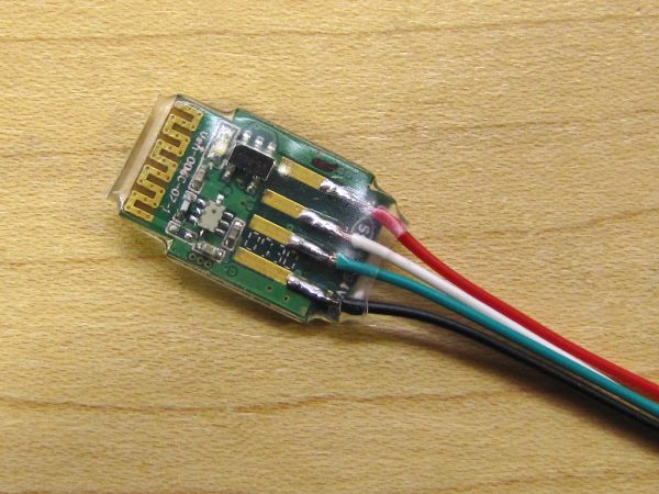
I soldered fine wires to the USB contacts, and then covered the adapter with heat shrinkable tubing.
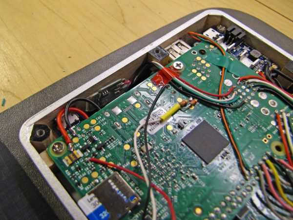
After connection to the USB terminals on the Pi board, the adapter was tucked into an empty area near one edge of the tablet and held in place with double-sided tape (not shown).
In order to use the external adapter, it was first necessary to disable the
built-in one by adding the following to the end of the
/boot/config.txt file:
dtoverlay=pi3-disable-bt
After rebooting, Raspbian automatically recognized the new adapter and was happy to pair with the keyboard and mouse, both of which functioned flawlessly. Although it’s too soon to say definitively, it seems that the built-in WiFi is also working better with the built-in Bluetooth disabled.
The adapter I used has long been discontinued, but the same technique should be applicable to any tiny Bluetooth adapter that is known to work with the Raspberry Pi.
Addendum November 2018: Real Time Clock Battery
A few weeks ago, I went to use my tablet after it had been idle for a while, only to find that the clock was showing the wrong time and date after booting. I opened up the tablet to find that the 3V lithium cell in the real time clock module was reading about 0.2V after only about a year of use. I had bought a total of three of these modules at the time, so I went and checked the others and found that their cells were also dead.
I placed an order for replacement cells from a seller on eBay, but while waiting for those to arrive, did some research on the DS3231 chip used in the clock module. It turns out that the allowable range of backup battery voltage is quite wide, so I decided to power it directly from the tablet’s main 3.7V lithium-ion battery instead of a dedicated cell.
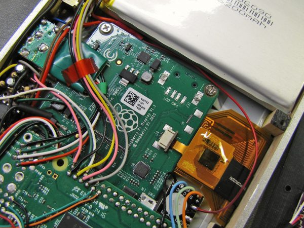
With the real time clock’s own battery removed, a thin red wire from the tablet battery’s positive connection directly feeds the real time clock.
To do this, I spliced an additional thin red wire to the connection between the positive terminal of the main battery and the tablet. Then, after removing the clock’s lithium cell, I connected this to where the positive terminal of the cell had been connected. While doing this, I had to be extremely careful to not allow the temporarily exposed positive connection to come into contact with any circuitry or metal parts in the tablet, as it could easily fry something (since the negative terminal was still connected to everything).
Related Articles
If you've found this article useful, you may also be interested in:
- MusicRack – A Digital Sheet Music Display System
- Make a Dual-Boot IDE Cable
- USB Powered AA NiMH and NiCd Battery Charger

If you've found this article useful, consider leaving a donation in Stefan's memory to help support stefanv.com
Disclaimer: Although every effort has been made to ensure accuracy and reliability, the information on this web page is presented without warranty of any kind, and Stefan Vorkoetter assumes no liability for direct or consequential damages caused by its use. It is up to you, the reader, to determine the suitability of, and assume responsibility for, the use of this information. Links to Amazon.com merchandise are provided in association with Amazon.com. Links to eBay searches are provided in association with the eBay partner network.
Copyright: All materials on this web site, including the text, images, and mark-up, are Copyright © 2025 by Stefan Vorkoetter unless otherwise noted. All rights reserved. Unauthorized duplication prohibited. You may link to this site or pages within it, but you may not link directly to images on this site, and you may not copy any material from this site to another web site or other publication without express written permission. You may make copies for your own personal use.


Michael Horne
July 14, 2017
What a tremendous account of a fantastic build. I want one 🙂
Dillon Nichols
July 14, 2017
Amazing attention to detail. Awesome project.
Adam Paul Sommer
July 14, 2017
Thanks for posting such great details of the steps. Been thinking about a Raspberry Pi laptop build for a while, and this is very inspiring.
Thanks again!
fred
July 15, 2017
What an inspiring labour of love! The stripping down unused parts thing gave me ideas for my own projects.
Andy from Workshopshed
July 15, 2017
Hey Stefan, what a great project. An excellent combination of electronics, software, woodwork and more.
Chris Barbieri
July 15, 2017
Fantastic! I especially love the pushbuttons made from old transistors. I too am a woodworker hobbyist and in this day of 3D- printed parts, it is nice to see wood being used.
Kirk Adair
July 15, 2017
Very nice, very good use of space
AndyJ
July 15, 2017
In appearance, it reminds me of a very basic metal-cased Android tablet I had a number of years ago. In ability, it’s in another league. Congratulations!
I realise I could go hunt the price for each component listed, but ignoring the huge amount of time put into this, do you have an idea the costs involved?
Stefan Vorkoetter
July 15, 2017
Hi Andy: I didn’t really keep track, but it was definitely more than I could have bought a tablet for. Probably somewhere in the $250 to $300 (Cdn) ballpark. Of course, some of the things I bought, like paints, I only used a tiny portion of on this project, and will use on other projects too.
Bob Murphy
July 15, 2017
WOW! An intense, elegant, creative labor of love and ingenuity. This has so many good ideas in it I’m going to save it to savor. Congratulations to you, Stefan.
FipS
July 15, 2017
Very nicely put together! I wouldn’t expect such a compact build when using standard components, great job. The wooden frame is also very nice. I’m building something similar based on Raspberry PI Zero W, but without a display, just a very portable wireless mini server, which can serve as a backend for my mobile/tablet on go.
JP
July 15, 2017
Contratulations Stefany,very nice. An excelent work that include wood, software programme, electronic services nand art.
Stéphane
July 16, 2017
Brilliant!
William H B Mawhinney
July 16, 2017
Excellent article!!
Freire
July 16, 2017
Congratulations, one of the best and thorough project for Raspberry Pi.
George V
July 17, 2017
Excellent work, very detailed, much appreciated for sharing the know how
Xiblack
July 17, 2017
Thorough article, detailed explanation and excellent results.
Thank you for sharing your work. It has practical usages for many pieces of hardware, software and diy stuffs.
Love the final look of your tablet.
H. Kamran
July 17, 2017
You could have used a Raspberry Pi Zero W. They are small, powerful, plus has wireless capabillites. The only difference is that is has a mini-USB for OTG support, and it has a camera port only. But you probably could have found a way to use the mini-HDMI port with the Raspberry Pi Foundation’s Display…
Stefan Vorkoetter
July 17, 2017
The Pi Zero W hadn’t been announced yet when I started, and I don’t think it’s trivial to convert HDMI to what the display is expecting. I’d probably need a Pi-3-sized converter board.
Brian
July 18, 2017
Does the tablet work in portrait and landscape mode?
Zander
July 18, 2017
May I suggest writing an LXPanel plugin for quick access to battery levels?
Stefan Vorkoetter
July 18, 2017
I haven’t tried it in portrait mode, but I don’t see why it wouldn’t. It would just be a matter of setting
lcd_rotatein the/boot/config.txtfile.Stefan Vorkoetter
July 18, 2017
I could do that (after figuring out how), but the dashboard app I wrote already gives that information in its taskbar icon anyway, so all it would do is save a tiny bit of real estate on the taskbar.
John
July 20, 2017
Wonderful Stefan! It has inspired me to have a go at something similar. Thanks for sharing.
Nayan
July 22, 2017
Hi stefan,
I’m also working on similar to this tablet and also using pi 3 , 7inch touchscreen display & powerboost 1000c but what I’m facing is that when i bootup the pi it restarts again & again coz the o/p voltage drops to 4.5V. I’m sure you also face this problem while making this tablet. Any suggestions about this problem??
It will be a great help for me!
Thanks
Stefan Vorkoetter
July 22, 2017
Hi Nayan,
The only time I had a problem was when the battery leads were too long and thin and could not supply enough current to the PowerBoost 1000C to maintain the desired output voltage under load. The leads should be short and/or thick.
Also, if the problem happens with the adapter connected, make sure the adapter can provide 5V at 2.5A. When the adapter is connected, it both powers the Pi, and charges the battery.
Forrest Dee Jeffcoat
July 22, 2017
My hardiest compliments upon your admirable accomplishments; and my sincere admiration.
Not the least, I’ve thoroughly enjoyed the ‘trip’ you’ve
shared in your adventure extent!
My best of wishes toward your next adventure!
A tip of the old Hatlo hat, as it were and Bon Voyage!
(wouldn’t have an open berth, perhaps, would you?)
Jeff
Juris Perkons
July 23, 2017
Super inspiring. I am electronics engineer and hobbyist, so, project like this gives me tons of emotions, thoughts, and gives dopamine dose to brain. Thank You a Big One.
kenC
July 23, 2017
This is Engineering Art. Not only fully functional but a classy silky style achieved from a lot of extra thought/effort resulting in a very professional and desirable piece of technology. It was a bit like observing someone modelling a new sports cars but there it is made out of some easy mouldable material. This is more a designer at work wearing an engineer’s hat and working with the hands of a craftsman. Should have a flash motif on the side! Perhaps….Ultimate_Pi.
Great stuff.
Javier Garcia
July 23, 2017
I want one!!! Lovely, nice, neat and sleek!!!
Nayan
July 25, 2017
Hi Stefan,
Thanks for the reply!
After connecting the wall adapter to PB 1000c the o/p voltage drops . while on battery the o/p voltage remains 5.01V. Kindly suggest
Stefan Vorkoetter
July 25, 2017
It sounds like your wall adapter is inadequate. What is the rated output current of the adapter?
Nayan
July 25, 2017
ok. my wall adapter is 5V 2A.
https://forums.adafruit.com/viewtopic.php?f=19&t=120685
I suggest u to read my conversation with adafruit guy, he is saying that PB 1000c is not suitable to powerup pi3 & 7″ display.
Andrew
July 25, 2017
Fantastic build, thanks for sharing!
Quick question, where did find your 6200mAh Lithium-polymer battery? I’m having trouble finding one.
Stefan Vorkoetter
July 25, 2017
Nayan, I will go participate in that conversation. The adapter should be adequate, although 5.2V at 2.5A would be better.
Stefan Vorkoetter
July 25, 2017
Andrew, search for “906090 battery” on eBay.
MAthieu BC
July 25, 2017
Great and really good job. A true step-by-step tutorial for raspberry and linux lover that love a freedom tablet. Because of this great tutorial, many people will have more software and true programming capability with the tablet instead to use an Intel computer for Android apps.
Nayan
July 26, 2017
yes u r ryt stefan!
I unplugged the battery from PB 1000c and power only by wall adapter the volts I measured from BAT pin was flicking b/w 4.67V – 5.01V which causes reboot of pi3 & display.
Stefan Vorkoetter
July 26, 2017
Oh oh. You should never run a PB1000C without the battery attached, as it will likely be damaged.
Mark F
July 28, 2017
Fantastic job. I love to see the work of a craftsman. Thank you.
Ben S
August 03, 2017
Thanks for sharing your building adventure. Outstanding work! Super cool!
MarkyD
August 10, 2017
What an awesome achievement, very impressive. Whats more impressive is that you have taken the time to document this is such a detailed and extensive manner. You have inspired me and I am sure others. Big thank you!
Wolfgang
August 18, 2017
Since I am currently working on my own Pi-Tablet -like device, this is a really great inspiration. Thank you for sharing!
JohnP
September 10, 2017
Great job – very inspiring. It appears you are a pilot, and so am I, so I was wondering if you have done anything with a PI ADS-B receiver? If so, have you published the information?
Thank You!
Stefan Vorkoetter
September 10, 2017
No, I haven’t done anything aviation related with the Pi (yet).
dwrz
January 07, 2018
Stefan, are you available to build one on order?
Stefan Vorkoetter
January 07, 2018
No, sorry, I’m not.
Mark C.
February 16, 2018
Great guide! I was going to build mine per Adafruit’s project but I like yours much better. Questions: the big LiPo battery from eBay, is it holding up well? Have you considered adding the R Pi camera?
Stefan Vorkoetter
February 21, 2018
Prompted by your question, I decided to do a discharge test. I fully charged the battery overnight, and then turned the tablet on and left it idle, with the screen at 50% brightness (the level at which I did all my earlier power consumption tests). It ran for a hair over 7 hours, which works out to 15Wh. The battery is supposed to be 23Wh (6.2Ah x 3.7V nominal). The only difference from my initial test conditions is that I have the on-board Bluetooth disabled and a USB Bluetooth adapter permanently connected. I never did such a test when I first installed the battery, so I don’t know how much it has degraded versus how far below spec it started out. All my initial tests were with an external 6.6Ah pack.
Regarding the camera, I had thought about it at first, but decided that a tablet doesn’t really need a camera, and I also couldn’t figure out how to fit it in.
Stefan Vorkoetter
February 21, 2018
I just discovered I had an old discharge log from shortly after I installed the battery. For the two parts of the discharge that the logs have in common (4.10V to 3.50V), the time went from 8:03 to 6:30. That suggests a ~20% reduction in capacity 8 months. I’m now going to fully recharge the tablet and try the discharge test again.
Stefan Vorkoetter
February 22, 2018
Okay, I’ve just done the discharge test again, after fully recharging after yesterday’s full discharge. The run time over the same voltage range is now 7:04. It seems that the battery had gotten lazy and was suffering from memory effect (yes, it turns out that lithium ion batteries do suffer from this: https://www.psi.ch/media/memory-effect-now-also-found-in-lithium-ion-batteries).
Mark C.
February 24, 2018
Thank you for those test results. I’m probably going to upgrade to a larger battery but am fearful of getting a bogus or inferior one as some have reported about LiPos from China and HK(generally.)
Given the tight space issues in the case I have considered making an externally mounted battery case given a flat enough cell.
Regarding the need for a camera in the tablet it’s a preference more than anything. Given the versatility of it from taking pics of documents to making it a surveillance cam with MotionEyeOS to being a 3D print server with OctoPrint.
I’ll be installing a tripod screw mount so that the unit can be as versatile as possible.
The hardest part of the build so far has been, wait for it, finding the right screws. Had to dig around in my spare screw box from years back when I disassembled everything broken I could get my hands on.
Gene J
March 20, 2018
Thanks for all your wisdom! I’m primarily a hardware & mechanical guy so your software wisdom is highly appreciated! I’ve had similar ideas and dislike the limitations of an ‘out of the box’ tablet. I know mine reflect changes to reflect my personal need but you’ve helped confirm by basic concepts. I already have a Pi3 waiting in the wings, just need a display to start tinkering.I’d love to learn more about the case you made…it’s similar to what’s been rattling around my mind 😉
allan
June 04, 2018
Any chance you can sell me this raspberry tablet? Kindly email me. Thanks
Stefan Vorkoetter
June 04, 2018
Sorry Allan, but it’s not for sale.
Simon
June 22, 2018
Great project, instructions and results! I’d like to build this. Is there any reason to not use the latest Pi3+? Or is it be better to stick with the original Pi3?
Stefan Vorkoetter
June 22, 2018
A Pi3+ would probably work and fit fine, but I can’t say for sure since I haven’t tried it. My only concern would be the slightly faster clock speed resulting in higher power consumption and more heat to get rid of.
Raymond
July 02, 2018
Great job and very well done.
Jesse
July 17, 2018
Very nice job! I found this write up after I purchased my parts. I’m going for a pi3b+ build, I was a little skeptical about the powerboost 1000 and 4400mah battery I went with, but after seeing your write up I am more optimistic.
Can you tell me what gauge wires you used for your power setup? Any other gotchas for making my setup work?
Stefan Vorkoetter
July 18, 2018
I didn’t check exactly what gauge they were, but they were taken from an old 3.5″ floppy drive power cable. Probably 18ga. Be sure to keep the wires between the battery and PowerBoost as short as possible. If the battery already has wires on it, they are probably too thin (mine were), so cut them as close to the battery as possible and attach the thicker wire there.
Jesse
July 19, 2018
What do you think about using two power boosts? Any concern with that? Jump from USB input to the others USB input. Dual batteries? Then one output goes to the display and the other the pi.
Stefan Vorkoetter
July 19, 2018
I wouldn’t use dual batteries, or if I did, I’d wire them in parallel. Otherwise your system will become useless when either battery is dead. But yes, using one for the Pi and one for the display would work. You should then NOT connect power wires from the Pi to the display (probably obvious, but worth mentioning).
Jesse
July 19, 2018
If using dual batteries would both boosts charge it or just one? That’s the issue I am concerned about.
Stefan Vorkoetter
July 19, 2018
Good point. I would use a PowerBoost 500 for the display. It doesn’t charge.
Jesse
July 21, 2018
I’m wondering if I could wire a 1000 (non c) to the battery that’s plugged into the 1000c. My only concern with that is what the voltage from the battery will be when it’s charging from the 1000c. I’ll have to take some measurements.
Stefan Vorkoetter
July 21, 2018
Yeah, this occurred to me the other day too. The 1000C, when connected to an external source of power, powers the Raspberry Pi (or whatever is connected to it) directly from the external source. The battery is no longer part of the power supply while it is being charged. If you have another 500 or 1000 attached to the same battery, then it might confuse the charger of the 1000C.
Jesse
July 29, 2018
So I completed my tablet. The dual powerboosts worked well, thanks for the help!
The purpose of my tablet is mainly for show and a conversation peice for my office that has dozens of engineers
https://ibb.co/kjcKET
https://ibb.co/cvmqM8
Stefan Vorkoetter
July 30, 2018
Very nice work! Glad I could help.
Refaat
August 02, 2018
Hi I have a question.
What pieces are used in this segment (Shutdown Controller and Battery Monitor)
I read the subject, but I did not understand how to make this piece
Is it possible to buy a similar piece of internet?
Stefan Vorkoetter
August 02, 2018
The parts are all listed in that section. I have also just added a component placement and stripboard trace layout diagram. As far as I know, there is no item like it available commercially, as it is very specific to the problem I was trying to solve.
Daniel
August 17, 2018
Hi, I’m really impressed by your design, and I’m trying to do something a little less complex on my own. I’m still confused by how you managed to get ~2A (to power both Pi3 and screen) from the PowerBoost 1000C (which, as far as I can tell, is rated at only 1A). Does it have to do with the trace that you severed on the PowerBoost 1000C? Is there something I’m not understanding here?
Thanks again for taking the time to do the write-up and upload pictures!
Stefan Vorkoetter
August 17, 2018
Hi Daniel. I didn’t get 2A from the PowerBoost. With the Pi reasonably busy (playing a YouTube video) and the screen at full brightness, the whole thing only uses 0.95A. That drops to about 0.53A with the screen at a comfortable brightness level (42/255). The recommendation of a 2A supply for a Pi 3 is merely to ensure that there is enough power for peripherals, and in the case of cheaper power supplies, that the voltage actually remains above 5V even at typical current consumption levels.
Daniel
August 21, 2018
Hi Stefan, thanks so much for taking the time to answer my question!
GW
September 23, 2018
Hi Stefan.
I have a few questions:
Q1:
In the “Schematic of the shutdown controller and battery monitor”, C2=220nF. In the cuitboard “Shutdown controller and battery monitor component placement (top)”, C2 = 22nF. Which should it be?
Q2:
In the picture of the “Completed battery monitor and shutdown monitor”, you have a capacitor soldered between R1 and R2, which you can see across the top of LM393. This capacitor seems to be missing in your schematic as well as in the stripboard layout. From the picture, it seems that the value of this capacitor is 104 = 100nF. Is this capacitor necessary? If so, is it indeed 100nF?
Stefan Vorkoetter
September 23, 2018
220nF is the correct one. I will fix the board layout when I get a chance. The extra capacitor is just a power supply bypass capacitor, probably not strictly necessary in this case, but I’m in the habit of putting them in. It is connected across pins 4 and 8 of the chip (via the connections to R1 and R2).
FGemini
November 07, 2018
Dude, this is an AMAZING diy job.
Really, it kicks asses.
GG <3
Craig
November 16, 2018
I would like to build a 10″ tablet, also based on a Raspberry Pi. Would the recently released Pi 3A+ be suitable for a tablet build?
Stefan Vorkoetter
November 17, 2018
Do you mean the Pi 3B+? It should work about as well as the regular Pi 3, but it might use a little bit more power due to the faster clock speed.
Craig
November 17, 2018
The newly released Raspberry Pi 3 Model A+ : https://www.raspberrypi.org/products/raspberry-pi-3-model-a-plus/
Stefan Vorkoetter
November 17, 2018
Sorry, I hadn’t heard about that one yet. It should work, but keep in mind it only has 512Mb of RAM instead of 1Gb, and only a single USB port.
Michael Muise
November 30, 2018
Hello, where can we buy this Raspberry Pi tablet and is it Android based?
Thank you, Michael
Stefan Vorkoetter
November 30, 2018
You can’t, and it isn’t.
Yon
December 23, 2018
Hi Stefan,
This is a seriously awesome build! Thanks so much for sharing. I’m building this for my niece, so I just want to build a more robust enclosure.
I’m still an electronics noobie, and was really battling to understand how the triangle wave generator part of your circuit worked. I feel like to I finally get it now, but using http://www.falstad.com/circuit/ to simulate the circuit really helped.
Here is a sim of your triangle wave generator: http://tinyurl.com/y8pues6z
Omar Al Qarra
January 29, 2019
Hi Stefan,
I have a quick question, is there a way you can possibly make a 3d model for this so I can be able to 3d print it? If you do agree to make the 3d model, can you make sure there aren’t any logos on it like the raspberry pi logo or any other logo. Thanks in advance.
Stefan Vorkoetter
January 29, 2019
Sorry, I don’t have time to do that. I’d have to completely disassemble it and measure everything, not to mention that some components are simply attached to others with small stand-offs, not the enclosure, so that wouldn’t be reflected in the model anyway.
Salman Sheikh
February 03, 2019
What is the dimension of your frame pieces in length and width?
Stefan Vorkoetter
February 04, 2019
They’re 16mm wide and 2.8mm thick. The long pieces are 195mm long, and the short pieces are 106.4mm long (112 – 2 * 2.8). However, I didn’t measure the lengths while cutting them. As you can see in the article, I built a jig around the screen, and then cut and adjusted the pieces to fit. I didn’t measure them now either; I just looked in the article.
DENIS DS
February 13, 2019
Great work, masterpiece!
Omar Al Qarra
February 16, 2019
Dear Stefan,
I have decided to create my own raspberry pi tablet. I bought most of the materials I need. I have the screen, Diet Raspberry Pi(I basically “trimmed the fat”), Tactical Push Buttons, usb extensions, powerboost, etc. Can you tell me how I would connect the raspberry pi to the powerboost without the shutdown controller + battery monitor? Would I still be able to monitor how much percentage is left in the battery without it?
Stefan Vorkoetter
February 17, 2019
Instructions on how to connect the PowerBoost to a Raspberry Pi are included in the PowerBoost documentation. You can just use a USB cable from the PowerBoost’s output connector to the Pi’s input connector. And no, without the battery monitor, you won’t be able to monitor the battery. The best you can do is connect the PB’s low-battery output (LBO) to a GPIO pin on the Pi and be aware of the fact that the battery is almost dead.
Grant
June 10, 2019
This is a wonderful build. I am basing my build on yours, but decided to use a Pi 3A+ to save removing headers, however I might need to use a usb hub! This has allowed me to make my build 1mm thinner too. I know you are a busy man, but do you think you could explain in your write up a little more about how you did your software bits? I have downloaded the files, but then I just do not know what to do! I am quite computer literate, but a little new to Pi! Thank you.
Stefan Vorkoetter
June 10, 2019
Glad to see someone else is attempting a build! For the daemon program, first install the required libraries (listed near the end of the readme), then just go to the source directory and type ‘make’. For the dashboard, first install Lazarus, open the project, and select Build from the Run menu.
Grant
June 14, 2019
Thank you for such a quick answer. 2 last questions! why did you go for saw tooth voltage monitor rather than an ADC (say MCP3002), could this still be read in the background? Secondly, would you be prepared to put an SD image up for download? Thank you again!
Stefan Vorkoetter
June 14, 2019
I used the sawtooth voltage monitor because it’s what I know, and I have dozens of LM393 comparator chips on hand. I also generally try to stay with generic parts in most of my designs, since proprietary chips tend to come and go. That said, a chip like the MCP3002 would certainly do the job. Of course the software in the daemon would have to be altered to suit.
As far as an image is concerned, I don’t think I want to do that. The image I have now is full of my own personal stuff, so to create one that is completely fresh-out-of-the-box would be a fair bit of work.
Grant
June 15, 2019
Thank you again. I respect your comments on the SD image.
I note that you connect the audio mixed signal to the + terminal of the PAM8302a amp. (Have you grounded the – ?). The reason I raise this is because I tried to use a single BC547b transistor as an amp (something which works fine on tone pins on Arduino). However it would not work. Eventually I discovered that the composite audio seems to come out below the zero Volt rail (i.e. negative). I therefore wonder whether you should use the other terminal on the amp? Hope I am not pestering you!
Stefan Vorkoetter
June 15, 2019
Audio (-) is connected to ground already on the Pi, as it is on the amp, and on most audio equipment for that matter. Audio signals are always +/- relative to ground. If you want to make a simple transistor amp, you need to capacitively couple it to a bias voltage about half the supply voltage, so that the transistor is working with, for example, 1.5 to 3.5V, instead of -1.0 to +1.0V. The output is then capacitively coupled to the speaker (which is expecting +/- voltages again).
grant
June 27, 2019
Thank you again.
I also have a DS3231, which is working, but I am struggling to find a method to update system time from it at boot. I have tried a number of things posted, but so far no luck. What command did you put in which file on your build, please?
Also if you have any pointers for MCP3002 on SPI (I know you are not doing this) It would be good!
Thank you again
Miro
August 22, 2019
Hi Stefan,
First of all its absolutely amazing to see how someone can do something like this. I didn’t notice a contact info on your web page but based on your inputs I would be very thankful for your opinion in general.
I am not at all an electrician but I am interested very much in technology. I perfectly understand you made the tablet for your needs. However in my case I used to buy for years always the best mobile possible but for many years now I can’t find anything “useful” enough”. I understand there are many people like you that are experts and can “find their way with IT” but I believe there are really a lot of people which should benefit from maybe projects you are capable of. Of course I guess majority of users are lambs and will use anything available on the market but maybe there is a way of making them also more able of using som e IT that can mainly serve them and not making them a slave.
I would consider writing this as useless but based on your right approach and fact you seem to be into projects for people I am wondering why not to use the energy you used into making something not just so interesting to many but making it even useful or possibly even easily profitable as I understand with the right skills it can be done “quite easily” or maybe with just a little more effort.
The main issue is these days users have the option to buy many type of devices(PlayStation,mobile,projector,watches,… but each for a specific purpose. As I have only two hands it’s logical and even impossible to wear all the devices at the same time. The result is it’s people getting just used to it and loosing their freedom in some way. I suppose it’s similar as you as IT expert finds his sollution not to be dependant on the given user setup. I believe by assembling some kind of new device that would be beneficial and effective can make even the big manufacturers change their ways and their approach as it’s better to have an active IT user or costumer that is using the products rather than carrying a lot of useless stuff or fighting always with connections and so on.
Too bad you use a smartphone only lately because many years ago an old mobile was easily attached to a tv for example and try it today(not using your special device). Hope you understand my point.
At first I had also the idea I want that tablet you made and maybe I can more easily make it more better for my needs. Of course it’s clear you are busy with your bussiness or projects and I am just wondering whether it’s not worth it to make some device capable of fulfilling not just your or few people needs but making it happen for really many and especially contribute and effect the IT freedom this way? I wouldn’t bother but I noticed many other of your projects mentioned on the site and it seems so efficient to boost this way many users to a level not fighting months with achieving only this but maybe opening the doors to them to some maybe other but I can imagine more interesting projects or raising their knowledge and user freedom. The main point is why not to assemble something that can place people to a different level and experts like you too and use the time then for other projects and not just for the basic tool or device. I would be really interested in your response if possible.Thank you very much.
In why case thanks again for your interesting input. Many regular daily problems can be solved quite easily which can effect things globally but I believe IT is special as it’s many times “invincible issues” so I guess mainly IT experts can change or have a moj effect…
Miro
August 23, 2019
Vyhledat
Raspberries pi 4 – discussion
M
mVrso .
komu já
před 1 minutouZobrazit podrobnosti
http://www.stefanv.com/electronics/a-compact-home-made-raspberry-pi-tablet.html#comment-482728
Hi Stefan,
First of all its absolutely amazing to see how someone can do something like this. I didn’t notice a contact info on your web page but based on your inputs I would be very thankful for your opinion in general.
I am not at all an electrician but I am interested very much in technology. I perfectly understand you made the tablet for your needs. However in my case I used to buy for years always the best mobile possible but for many years now I can’t find anything “useful” enough”. I understand there are many people like you that are experts and can “find their way with IT” but I believe there are really a lot of people which should benefit from maybe projects you are capable of. Of course I guess majority of users are lambs and will use anything available on the market but maybe there is a way of making them also more able of using som e IT that can mainly serve them and not making them a slave.
I would consider writing this as useless but based on your right approach and fact you seem to be into projects for people I am wondering why not to use the energy you used into making something not just so interesting to many but making it even useful or possibly even easily profitable as I understand with the right skills it can be done “quite easily” or maybe with just a little more effort.
The main issue is these days users have the option to buy many type of devices(PlayStation,mobile,projector,watches,… but each for a specific purpose. As I have only two hands it’s logical and even impossible to wear all the devices at the same time. The result is it’s people getting just used to it and loosing their freedom in some way. I suppose it’s similar as you as IT expert finds his sollution not to be dependant on the given user setup. I believe by assembling some kind of new device that would be beneficial and effective can make even the big manufacturers change their ways and their approach as it’s better to have an active IT user or costumer that is using the products rather than carrying a lot of useless stuff or fighting always with connections and so on.
Too bad you use a smartphone only lately because many years ago an old mobile was easily attached to a tv for example and try it today(not using your special device). Hope you understand my point.
At first I had also the idea I want that tablet you made and maybe I can more easily make it more better for my needs. Of course it’s clear you are busy with your bussiness or projects and I am just wondering whether it’s not worth it to make some device capable of fulfilling not just your or few people needs but making it happen for really many and especially contribute and effect the IT freedom this way? I wouldn’t bother but I noticed many other of your projects mentioned on the site and it seems so efficient to boost this way many users to a level not fighting months with achieving only this but maybe opening the doors to them to some maybe other but I can imagine more interesting projects or raising their knowledge and user freedom. The main point is why not to assemble something that can place people to a different level and experts like you too and use the time then for other projects and not just for the basic tool or device. I would be really interested in your response if possible.Thank you very much.
In why case thanks again for your interesting input. Many regular daily problems can be solved quite easily which can effect things globally but I believe IT is special as it’s many times “invincible issues” so I guess mainly IT experts can change or have a moj effect…
Bert van de Beek
February 05, 2020
Thank you for this really amazing and inspiring article !!
JazekerXX
April 01, 2020
What a cool project! very nicely made.
if i may give you some tips?
i think you will be very happy if you buy a 3D printer, a project like this tablet is 100 times easier to make (with extreme accuracy) with a 3D printer. for designing your 3D object you can use tinkercad, this is an extreme easy to learn programm. follow a tutorial and 5 minutes later you can design in 3D too!
also if you want to make PCB’s (printed circuit boards) JLCPCB makes very good quality for low prices, they also have a SMT assembly service so you don’t have to solder all those tiny components yourself.
to design PCB’s i use EasyEDA, this is a fairly easy to use programm but you have to practice a bit.. if you want to use the smt assemble service of JLCPCB, you’d best use the parts list at https://jlcpcb.com/parts copy the selected LCSC part number (starting with Cxxxxxx) and search the library of EasyEDA to get the right schematic symbol with corresponding pcb footprint..
i hope these tips will get your projects to the next level!
happy building.
best regards
Stefan Vorkoetter
April 01, 2020
Thanks for the tips. I don’t really see any benefit though. 3D printing something is no fun compared to building it with your own hands. As far as PCBs go, I only make those when I want to make more than one of something, and when I do, I use my own PCB design software, and then mark the boards by hand before etching them.
Adam savage chipman
June 05, 2020
What a tremendous and detailed build;
MAKE SURE YOU CONTACT ME!EMAIL ME.
It’s business.
Savage.A
mamaligadoc
December 27, 2020
With respect !!!
Al Ik
August 02, 2021
Hey Stefan
Thanks for the great work; you are genius!
I am probably seeing this too late as may now be too occupied; not that you were not before now. I am thinking of rending this in android; someone may have already done that though but I want to try.
Deddi Carles
March 08, 2022
Nice Job!
I love it!
I hope i can build one with 10 inch LCD display and maybe with 3d printed case or aluminum case.
Thanks for the article!
Anthpect101
January 06, 2024
Cool project! Anyways, can you list all of the components? The only difference I will make is an Raspberry PI Zero W, headphone jack (no built-in speakers for some reasons), built-in SDR with antenna outside (for strong wireless stuff). Thank you.