Low-Sensitivity Sallen-Key Filter Design with the HP-67 Programmable Calculator
December 12, 2008
This program, a part of my series of analog electronic design programs for the HP-67 programmable calculator, addresses the problem of designing second order single op-amp low- and high-pass filters using the Sallen-Key topology.
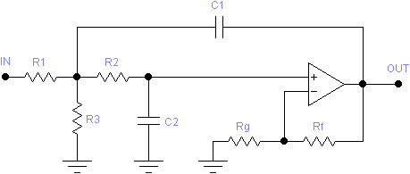
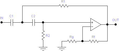
The Sallen-Key filter topology has the advantage of using a minimum of components. The simplest Sallen-Key filters use only two resistors and two capacitors. Additional resistors may be added for input attenuation (low-pass only) and gain adjustment. The following schematics illustrate these generalized Sallen-Key circuits:
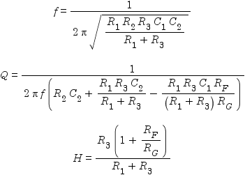
The equations governing the low-pass filter are as follows,
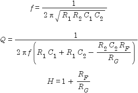
where f is the filter’s cut-off frequency, Q is its “quality”, and H is its gain at the cut-off frequency. The corresponding equations for the high-pass filter are:
The mathematically inclined will notice that in each case, there are three equations in either nine or ten variables. Thus there is no single “right” solution. At least six or seven of the variables have to be decided arbitrarily (f, Q, H, and three or four component values), at which point the remaining variables (component values) can be solved for. An article by Texas Instruments suggests a number of simplifications to help one choose component values, but this just adds the complication of which simplification to choose.
I recently came across a pair of application notes by National Semiconductor which gives a procedure for designing Sallen-Key filters to minimize the effect of component value tolerances on the performance of the filter. A side-effect of this procedure is to reduce the number of inputs to five: f, Q, H, RF, and R, where the latter is simply an indication of the magnitude of resistor values desired for R1, R2, and R3. The procedure then dictates how all the other values are chosen, even adjusting for available “real-world” values part way through the solution.
The program presented here implements this procedure, with some minor changes:
-
Instead of asking for a desired resistor magnitude, R, the program asks for a capacitor magnitude, C, since in my experience, the capacitors drive the design.
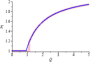
- The formula given for internal gain variable K in the procedure (please refer to the application note) seems to have been derived empirically, and has a jump at Q = 1.1. To make the formula simpler to implement, I modified it slightly to:
The graphs of the original (pink) and revised (blue) formulae show the difference. Testing has shown that the resulting solution is generally at most one real-world capacitor value increment different (with corresponding changes in resistor values of course).
Also, if H > K, then K is set equal to H, since otherwise it will not be possible to achieve the desired gain.
For the low-pass circuit, the desired gain, H, is achieved by a combination of input attenuation, α (controlled by R1 and R3), and the internal gain, K, of the filter (controlled by RF and RG). The division of this gain between the two stages depends on H and Q and is chosen to minimize the sensitivity of the circuit to component tolerances. For example, for H = 1 and Q = 2, the attenuator gain is α = 0.629 and the internal gain is K = 1.59, for a net gain of H = αK = 1.
The high-pass circuit has no attentuation stage, so H must be at least 1, and higher for Q > 0.917. If too low a value is entered for H, it is increased as necessary to make the circuit solvable.
For either circuit, to achieve a result with minimum component sensitivity without regard to gain, set H = 0. The program will automatically choose the optimal value for K (and thus H). The resulting gain will be output when determining the performance.
Using the Program
First type in the program and save it, or read it from a previously recorded magnetic card. The card should be labelled as follows:
| LOW-SENSITIVITY SALLEN-KEY FILTER DESIGN | ||||
|---|---|---|---|---|
| f | Q | H | C | RF |
| LP→RGC1C2R1R2R3 | HP→RGC1C2R1R2 | →f,Q,H | ||
Filter Design from Specifications
Example: Design a 500Hz low-pass unity-gain filter with a Q of 2, using capacitors in the 10nF range, and a 47kΩ resistor for RF:
| Description | Keystrokes | Display |
|---|---|---|
| Use engineering notation | h ENG DSP 2 |
0.00 00 |
| Enter f | 500 f a |
500. 00 |
| Enter Q | 2 f b |
2.00 00 |
| Enter H | 1 f c |
1.00 00 |
| Enter C | 10 EEx CHS 9 f d |
10.0 -09 |
| Enter RF | 47 EEx 3 f e |
47.0 03 |
| Compute RG | A | 79.5 03 |
| Enter real-world RG and compute C1 | 82 EEx 3 R/S |
31.6 -09 |
| Enter real-world C1 and compute C2 | 33 EEx CHS 9 R/S |
3.16 -09 |
| Enter real-world C2 and compute R1 | 3.3 EEx CHS 9 R/S |
15.4 03 |
| Enter real-world R1 and compute R2 | 15 EEx 3 R/S |
95.9 03 |
| Enter real-world R2 and compute R3 | 100 EEx 3 R/S |
26.1 03 |
| Enter real-world R3 | 27 EEx 3 R/S |
27.0 03 |
Notes
If a resistor is to be omitted (open circuit), this program displays a value of zero for the resistance. This is different than some of my other programs, which display a “large” value representing infinity.
When the value for RG is displayed as zero, meaning it can be omitted, the value of RF will not matter any more, and RF can be replaced by a direct connection.
Filter Performance from Chosen Components
During the calculation of the solution above, we’ve entered real-world values in response to each computed value. The real-world values of C1 and C2 are used when computing the values of R1, R2, and R3. However, the real-world values of each of those resistors does not affect the computed value of the remaining ones. Thus, the final filter may not perform exactly as specified. To find out how it does perform, follow these steps:
| Description | Keystrokes | Display |
|---|---|---|
| Compute resulting f | E | 491. 00 |
| Compute resulting Q | R/S | 1.86 00 |
| Compute resulting H | R/S | 1.01 00 |
A High-Pass Example
Using the parameters already entered for the low-pass filter above, determine the components for a high-pass filter:
| Description | Keystrokes | Display |
|---|---|---|
| Compute RG for high-pass filter | C | 79.5 03 |
| Enter real-world RG and compute C1 | 82 EEx 3 R/S |
31.4 -09 |
| Enter real-world C1 and compute C2 | 33 EEx CHS 9 R/S |
3.18 -09 |
| Enter real-world C2 and compute R1 | 3.3 EEx CHS 9 R/S |
9.59 03 |
| Enter real-world R1 and compute R2 | 10 EEx 3 R/S |
97.0 03 |
| Enter real-world R2 | 100 EEx 3 R/S |
0.00 00 |
Now determine the predicted actual performance:
| Description | Keystrokes | Display |
|---|---|---|
| Compute resulting f | E | 482. 00 |
| Compute resulting Q | R/S | 1.96 00 |
| Compute resulting H | R/S | 1.57 00 |
Notice that H is higher than the specified unity gain. This is because the filter is not possible to construct with unity gain when Q = 2. The smallest possible gain is H = 1.59 (which due to real-world components, has become Q = 1.89 and H = 1.57). To achieve H = 1, you will need either a pre-attenuator with low output impedance, or a post-attenuator with high input impedance.
Program Listing
| Line | Instruction | Comments |
|---|---|---|
| 001♦ | LBL a | Enter and store f |
| 002 | STO A | |
| 003 | RTN | |
| 004♦ | LBL b | Enter and store Q |
| 005 | STO B | |
| 006 | RTN | |
| 007♦ | LBL c | Enter and store H (gain) |
| 008 | STO C | |
| 009 | RTN | |
| 010♦ | LBL d | Enter and store C (capacitor scale) |
| 011 | STO 0 | |
| 012 | RTN | |
| 013♦ | LBL e | Enter and store RF |
| 014 | STO 4 | |
| 015 | RTN | |
| 016♦ | LBL A | Low-pass filter: RG,C1,C2,R1,R2,R3 |
| 017 | CF 0 | |
| 018 | GTO 0 | |
| 019♦ | LBL C | High-pass filter: RG,C1,C2,R1,R2 |
| 020 | SF 0 | |
| 021♦ | LBL 0 | Forward solution |
| 022 | RCL B | |
| 023 | 2 | |
| 024 | . | |
| 025 | 2 | |
| 026 | × | |
| 027 | . | |
| 028 | 9 | |
| 029 | − | |
| 030 | RCL B | |
| 031 | . | |
| 032 | 2 | |
| 033 | + | |
| 034 | ÷ | (2.2Q-0.9)/(Q+0.2) |
| 035 | 1 | |
| 036 | x≤y? | |
| 037 | x↔y | |
| 038 | STO E | K = max(1,(2.2Q-0.9)/(Q+0.2)) |
| 039 | RCL C | |
| 040 | x>y? | |
| 041 | STO E | K = max(H,1,(2.2Q-0.9)/(Q+0.2)) |
| 042 | RCL E | |
| 043 | ÷ | H/K |
| 044 | x=0? | |
| 045 | 1 | Use α = 1 if H/K = 0 (because H was 0) |
| 046 | F? 0 | |
| 047 | 1 | Always use α = 1 for a high-pass filter |
| 048 | STO D | α = H/K (always 1 for a high-pass filter or H = 0) |
| 049 | RCL 4 | |
| 050 | RCL E | |
| 051 | 1 | |
| 052 | − | |
| 053 | x≠0? | |
| 054 | ÷ | RG = RF/(K-1) if K ≠ 1, or zero if K = 1 |
| 055 | R/S | Display RG and let user change it |
| 056 | STO 5 | |
| 057 | . | Initialize n to √0.1 |
| 058 | 1 | |
| 059 | √x | |
| 060 | GSB 7 | n(1+√(1+4Q2(1+n2)(K-1)))/(2Q(1+n2)) |
| 061 | RCL 8 | √0.1 was stored here by subroutine 7 |
| 062 | x≤y? | |
| 063 | x↔y | max(n, n(1+√(1+4Q2(1+n2)(K-1)))/(2Q(1+n2))) |
| 064 | F? 0 | High-pass filter? |
| 065 | GSB 6 | 2nQ/(1+√(1+4Q2(K-1-n2))) |
| 066 | STO 8 | |
| 067 | RCL 0 | |
| 068 | RCL 8 | |
| 069 | ÷ | C1 = C/n |
| 070 | R/S | Display C1 and let user change it |
| 071 | STO 6 | |
| 072 | RCL 8 | |
| 073 | RCL 0 | |
| 074 | × | C2 = nC |
| 075 | R/S | Display C2 and let user change it |
| 076 | STO 7 | |
| 077 | RCL 6 | |
| 078 | × | |
| 079 | √x | √(C1C2) |
| 080 | GSB 4 | Multiply by 2πf and take reciprocal |
| 081 | STO 9 | N = 1/(2πf√(C1C2)) |
| 082 | RCL 7 | |
| 083 | RCL 6 | |
| 084 | ÷ | |
| 085 | √x | n = √(C2/C1) |
| 086 | GSB 3 | 2nQ/(1+√(1+4Q2(K-1-n2))) or n(1+√(1+4Q2(1+n2)(K-1)))/(2Q(1+n2)) |
| 087 | STO 8 | |
| 088 | RCL 9 | |
| 089 | × | |
| 090 | STO 3 | (R1||R3) = nN |
| 091 | RCL D | |
| 092 | ÷ | R1 = (R1||R3)/α |
| 093 | R/S | Display R1 and let user change it |
| 094 | STO 1 | |
| 095 | RCL 9 | |
| 096 | RCL 8 | |
| 097 | ÷ | R2 = N/n |
| 098 | R/S | Display R2 and let user change it |
| 099 | STO 2 | |
| 100 | RCL 3 | |
| 101 | 1 | |
| 102 | RCL D | |
| 103 | − | ( 1-α (R1||R3) ) |
| 104 | x≠0? | |
| 105 | ÷ | R3 = (R1||R3)/(1-α) if α ≠ 1, or zero otherwise |
| 106 | R/S | Display R3 and let user change it |
| 107 | STO 3 | |
| 108 | RTN | |
| 109♦ | LBL 4 | Multiply by 2πf and take reciprocal |
| 110 | RCL A | f |
| 111 | × | |
| 112♦ | LBL 1 | Multiply by 2π and take reciprocal |
| 113 | 2 | |
| 114 | × | |
| 115 | π | |
| 116 | × | |
| 117 | 1/x | |
| 118 | RTN | |
| 119♦ | LBL 3 | Compute either 2xQ/(1+√(1+4Q2(K-1-x2))) or x(1+√(1+4Q2(1+x2)(K-1)))/(2Q(1+x2)) |
| 120 | F? 0 | High-pass filter? |
| 121 | GTO 7 | |
| 122♦ | LBL 6 | Subroutine to compute 2xQ/(1+√(1+4Q2(K-1-x2))) |
| 123 | STO 8 | Save x for later use |
| 124 | RCL B | |
| 125 | 2 | |
| 126 | × | ( 2Q x ) |
| 127 | × | ( 2xQ ) |
| 128 | LSTx | ( 2Q 2xQ ) |
| 129 | x2 | ( 4Q2 2xQ ) |
| 130 | RCL E | |
| 131 | 1 | |
| 132 | − | |
| 133 | RCL 8 | |
| 134 | x2 | |
| 135 | − | ( K-1-x2 4Q2 2xQ ) |
| 136 | × | ( 4Q2(K-1-x2) 2xQ ) |
| 137 | GSB 9 | ( 1+√(1+4Q2(K-1-x2)) 2xQ ) |
| 138 | ÷ | |
| 139 | RTN | |
| 140♦ | LBL 7 | Subroutine to compute x(1+√(1+4Q2(1+x2)(K-1)))/(2Q(1+x2)) |
| 141 | STO 8 | Save x in register 8 for later use both by this subroutine and the caller |
| 142 | GSB 8 | ( 2Q 1+x2 ) |
| 143 | x2 | |
| 144 | × | ( 4Q2(1+x2) ) |
| 145 | RCL E | |
| 146 | 1 | |
| 147 | − | ( K-1 4Q2(1+x2) ) |
| 148 | × | ( 4Q2(1+x2)(K-1) ) |
| 149 | GSB 9 | ( 1+√(1+4Q2(1+x2)(K-1)) ) |
| 150 | RCL 8 | |
| 151 | × | ( x(1+√(1+4Q2(1+x2)(K-1))) ) |
| 152 | RCL 8 | |
| 153 | GSB 8 | ( 2Q 1+x2 x(1+√(1+4Q2(1+x2)(K-1))) ) |
| 154 | × | ( 2Q(1+x2) x(1+√(1+4Q2(1+x2)(K-1))) ) |
| 155 | ÷ | |
| 156 | RTN | |
| 157♦ | LBL 8 | Subroutine to populate stack with 2Q 1+x2 |
| 158 | x2 | |
| 159 | 1 | |
| 160 | + | |
| 161 | RCL B | |
| 162 | 2 | |
| 163 | × | |
| 164 | RTN | |
| 165♦ | LBL 9 | Subroutine to compute 1+√(1+x) |
| 166 | 1 | |
| 167 | + | |
| 168 | √x | |
| 169 | 1 | |
| 170 | + | |
| 171 | RTN | |
| 172♦ | LBL E | Compute actual f, Q, and Gain |
| 173 | GSB 2 | R1 or (R1||R3) |
| 174 | RCL 6 | |
| 175 | × | |
| 176 | STO 8 | Save R1C1 for use in calculating Q |
| 177 | RCL 2 | |
| 178 | RCL 7 | |
| 179 | × | |
| 180 | STO 9 | Save R2C2 for use in calculating Q |
| 181 | × | |
| 182 | √x | |
| 183 | GSB 1 | Multiply by 2π and take reciprocal |
| 184 | ST I | Save actual f for use in calculating Q |
| 185 | R/S | Display actual f |
| 186 | RCL 9 | ( R2C2 ) |
| 187 | RCL 8 | ( R1C1 R2C2 ) |
| 188 | F? 0 | High-pass filter? |
| 189 | x↔y | ( R2C2 R1C1 ) |
| 190 | 1 | |
| 191 | RCL E | |
| 192 | − | |
| 193 | × | |
| 194 | + | |
| 195 | GSB 2 | R1 or (R1||R3) |
| 196 | RCL 7 | |
| 197 | × | |
| 198 | + | |
| 199 | RC I | Recall actual frequency |
| 200 | × | |
| 201 | GSB 1 | Multiply by 2π and take reciprocal |
| 202 | R/S | Display actual Q |
| 203 | RCL 4 | |
| 204 | RCL 5 | |
| 205 | x≠0? | |
| 206 | ÷ | |
| 207 | 1 | |
| 208 | + | |
| 209 | GSB 2 | R1 or (R1||R3) |
| 210 | × | |
| 211 | RCL 1 | |
| 212 | ÷ | |
| 213 | RTN | Return actual Gain |
| 214♦ | LBL 2 | Return either R1 or (R1||R3) |
| 215 | RCL 1 | |
| 216 | F? 0 | High-pass filter? |
| 217 | RTN | Return just R1 |
| 218 | 1/x | |
| 219 | RCL 3 | |
| 220 | x≠0? | R3 exists? (0 means not) |
| 221 | 1/x | |
| 222 | + | |
| 223 | 1/x | |
| 224 | RTN |
Registers and Flags
| Register | Use |
|---|---|
| 0 | C – capacitor scale |
| 1,2,3 | R1, R2, R3 – filter resistors |
| 4,5 | RF, RG – feedback resistors |
| 6,7 | C1, C2 – capacitors |
| 8 | n – variable used during computation |
| 9 | N – variable used during computation |
| A | f – cutoff frequency |
| B | Q – filter quality |
| C | H – overall gain |
| D | α – input attenuator gain |
| E | K – internal gain |
| I | Temporary register |
| Flag | Meaning |
|---|---|
| 0 | High-pass filter |
Revision History
2008-Dec-12 — Initial release.
References
1. Analysis of the Sallen-Key Architecture (Rev.B), Texas Instruments Application Report SLOA024B, James Karki, 2002
2. Low-Sensitivity, Lowpass Filter Design, National Semiconductor (now Texas Instruments) Application Note OA-27, Kumen Blake, 1996
3. Low-Sensitivity, Highpass Filter Design, National Semiconductor (now Texas Instruments) Application Note OA-29, Kumen Blake, 1996
Related Articles
If you've found this article useful, you may also be interested in:
- Op-Amp Gain and Offset Design with the HP-41C Programmable Calculator
- Op-Amp Oscillator Design with the HP-41C Programmable Calculator
- Low-Sensitivity Sallen-Key Filter Design with the HP-41C Programmable Calculator
- Op-Amp Gain and Offset Design with the HP-67 Programmable Calculator
- Op-Amp Oscillator Design with the HP-67 Programmable Calculator
- Resistor Network Solver for the HP-67 Programmable Calculator
- A Matrix Multi-Tool for the HP 35s Programmable Calculator
- Curve Fitting for the HP 35s Programmable Calculator

If you've found this article useful, consider leaving a donation in Stefan's memory to help support stefanv.com
Disclaimer: Although every effort has been made to ensure accuracy and reliability, the information on this web page is presented without warranty of any kind, and Stefan Vorkoetter assumes no liability for direct or consequential damages caused by its use. It is up to you, the reader, to determine the suitability of, and assume responsibility for, the use of this information. Links to Amazon.com merchandise are provided in association with Amazon.com. Links to eBay searches are provided in association with the eBay partner network.
Copyright: All materials on this web site, including the text, images, and mark-up, are Copyright © 2026 by Stefan Vorkoetter unless otherwise noted. All rights reserved. Unauthorized duplication prohibited. You may link to this site or pages within it, but you may not link directly to images on this site, and you may not copy any material from this site to another web site or other publication without express written permission. You may make copies for your own personal use.
